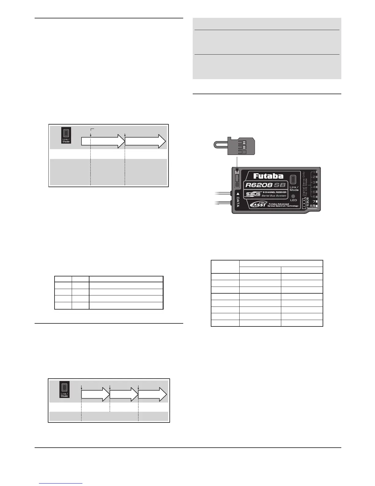
S.BUS Servo Channel Setting Method
S.BUS
servo channel setting can be performed at the
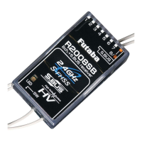
R6208SB
receiver.
1
Connecttheaccessoryshort-plugtothe
DATA
portof
the receiver.
Short-plug
(accessory)
* Connect the short-plug to the DATA port only when an S.BUS servo
channel is set. Normally do not connect the plug.
2
Connectan
S.BUS
servo to the conventional system
output connector(
1
to
8
) corresponding to the channel
you want to set.
Output
connector
Channelsetting
Mode A ModeB
1 1 9
2 2 10
3 3 11
4 4 12
5 5 13
6 6 14
7 7 15
8 8 16
* Channel setting mode A (ch1 to 8 setting mode) or channel setting
mode B (ch9 to 16 setting mode) can be set.
3
Turnonthereceiver.
* At once when turning on the receiver, the channel setting is com-
pleted in mode A.
(ToswitchtomodeB,pressthe
Link/Mode
button until
the red and green
LED
starts to blink simultaneously.
ThechannelsettingiscompletedinmodeB.)
* The LED corresponding to the setting mode blinks.
Mode A: Red blinks 3 times
Mode B: Green blinks 3 times
4
Turnoffthereceiver.
Operation Mode Select
The operation mode is on "Normal mode" from factory
shipping. When to change the mode, please follow the steps
shown below.
1
Turnoffthereceiver.
2
Press and hold the
Link/Mode
switch and turn on the
receiver. Keep the switch hold more than one(1)
second.The
LED
starts flashing with the current
status.
3
Release the switch.
4
Turnoffthereceiver.
By doing this step, the mode can switch over between two(2)
modes.
0 to 1 sec. More than 1 sec.
0 sec. 1 sec.
Press and Hold
Turn on the receiver.
No function
Showing the CURRENT
mode with blink.
Red Blink = Normal
Green/Red Blink =
High Speed
Solid as the mode changed.
Red Solid = Normal
Green/Red Solid = High
Speed
(Become Red after one (1)
second)
(Function)
To change the mode between
Normal and High Speed
(LED
Status)
Please check the operation mode by observing the
LED
when
turning on the receiver. If possible there's no
FASST
transmitter
turned on around you in order to make rmer check.
When turn on the receiver, the
LED
will be;
•Redwhenon"Normalmode"
•GreenandRed(makesOrange)whenon"HighSpeedmode".
(Aftertwo(2)seconds,changetoRed.)
If there are some
FASST
transmitter turned on around the
receiver, the
LED
may show the above status for a brief
moment then changed to the status indication as shown in the
"
LED
indication" table.
LED Indication
Green Red Status
Solid Solid Initializing
Off Solid Nosignalreception
Solid Off Receiving signals
Blink Off Receiving signals but ID is unmatched
Link to the transmitter
1
Press and hold the
Link/Mode
switchmorethantwo(2)
seconds.
Re-adjust the F/S position (only for TM-8)
1
Press and hold the
Link/Mode
switch between one(1)
andtwo(2)seconds.
0 to 1 sec. 1 to 2 sec. More than 2 sec.
0 sec. 1 sec. 2 sec.
Press and Hold
No function
With TM-8
(not included in this set)
To set the F/S
position(No re-link)
Re-link(ID set) and to
set the F/S position
No function
Other than TM-8
(not included in this set)
Re-link(ID set)
WARNING
Do not perform the linking procedure with
motor's main wire is connected or the engine is
operating as it may result in serious injury.
While the linking is done, please cycle receiver
power andcheckifthe receivertobe linkedis
really under the control by the transmitter to be linked.
FUTABA CORPORATION
1080 Yabutsuka, Chosei-mura, Chosei-gun, Chiba-ken, 299-4395, Japan
Phone: +81 475 32 6982, Facsimile: +81 475 32 6983
1M23N17434 ©FUTABA CORPORATION 2010, 10 (1)
 Loading...