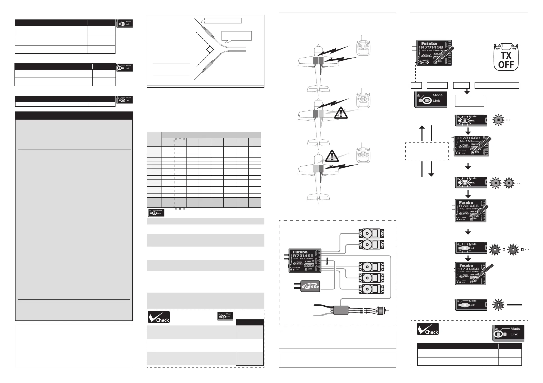
Port
Channel
Mode A Mode B Mode C Mode D Mode E Mode F Mode G Mode H
1 1 1 1 1 13 13 13 13
2 2 2 2 2 14 14 14 14
3 3 3 3 3 15 15 15 15
4 4 4 4 4 16 16 16 16
5 5 5 5 5 17 17 17 17
6 6 6 6 6 18 18 18 18
7 7 7 7 7 19 19 19 19
8 8 8 8 8 20 20 20 20
9 9 9 9 9 21 21 21 21
10 10 10 10 10 22 22 22 22
11 11 11 11 11 23 23 23 23
12 12 12 12 12 24 24 24 24
SB2/DG1 DG1 SB2 DG1 SB2 DG1 SB2 DG1 SB2
SB/DG2 DG2 SB SB DG2 DG2 SB SB DG2
LED RED 1 RED 2 RED 3 RED 4 RED 5 GREEN1 GREEN2 GREEN3
Default
Communicate with two receivers
Receiver : A Receiver : B
Even if there is a problem with
the B receiver, communication
will be performed with the A
receiver.
Even if there is a problem with
the A receiver, communication
will be performed with the B
receiver.
In Dual RX link mode, the SB2/RX port is for reception
only, so
u
se separate ports for S.BUS output and S.BUS2
input/output.
When using ESC
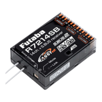
FASSTest Receiver
S.BUS2
R7314SB
ESC
Antenna
installation
Do not bend the antenna part
Antenna part
Gently bend the coaxial
cable part.
Coaxial cable
R7314SB CH Mode table
1
Turn on the receiver. [Transmitter is always OFF]
2
Press and hold the SW for 5 seconds to 10 seconds.
3
When the LED of the receiver changes from blinking
red to blinking orange, SW is released.
4
The LED should now blink red two times in the
patterns described in the chart below.
5
Each press of the SW advances the receiver to the
next mode.
6
When you reach the mode that you wish to operate
in, press and hold the SW for more than 2 seconds.
When LED blinks in orange, it is the completion of a
mode change, SW is released.
7
Cycle the receiver power o and back on again after
changing the Channel mode.
Channel Modes
The R7314SB is capable of changing its channel allocations
as described in the table below. This is especially important
when using the receiver in a dual receiver mode. See
your transmitter operation manual for complete details on
operating in the dual receiver mode.
Dual Rx Link System
By installing two receivers in one aircraft, if one receiver
becomes unable to communicate, the other receiver can be
operated.
Connection example
Antenna should be secured so
that it cannot move around or
back inside of aircraft.
In Dual RX Link Mode
In FASSTest12CH Telemetry OFF Mode
Status MODE LED
External receiver is receiving error or not connected.
S.BUS signal not received
Red Solid
S.BUS signal reception from external receiver
(also received by external receiver)
Green Solid
Status LINK LED
Start Orange Solid
Compliance Information Statement (for Canada)
This device complies with Industry Canada license-exempt RSS standard(s). Operation is subject to the
following two conditions: (1) this device may not cause interference, and (2) this device must accept any
interference, including interference that may cause undesired operation of the device. This equipment com-
plies with IC radiation exposure limits set forth for an uncontrolled environment. This equipment should be
installed and operated with minimum distance 20cm between the radiator & your body.
French: Cet appareil radio est conforme au CNR-210 d’Industrie Canada. L’utilisation de ce dispositifest
autorisée seulement aux deux conditions suivantes : (1) il ne doit pas produire de brouillage, et (2) l’utilisateur
du dispositif doit être prêt à accepter tout brouillage radioélectrique reçu, même sice brouillage est suscep-
tible de compromettre le fonctionnement du dispositif. Cet équipement est conforme aux limites d’exposition
aux rayonnements IC établies pour un environnement non contrôlé.
Cet équipement est conforme aux limites d’exposition aux rayonnements IC établies pour un environnement
non contrôlé. Cet équipement doit être installé et utilisé avec un minimum de 20 cm de distance entre la
source de rayonnement et votre corps
.
FASSTest is a bidirectional communication system
between the R7314SB receiver and FASSTest capable
transmitters. Multiple optional telemetry sensors may be
connected to the S.BUS2 on the receiver and that data is in
turn displayed on the transmitter.
Link to the transmitter
1
Bring the transmitter and the receiver close to
each other, within 20 inches (half meter).
2
Turn on the transmitter. Place the transmitter into
the receiver linking mode.
3
Turn on the receiver.
4
The receiver will wait for the linking process to
begin for 2 seconds. Following that it will return
to the normal operation mode.
5
When the LED of the receiver changes from
blinking red to solid green, linking is complete.
(A link waiting state is ended in 3 second.)
• Refer to the transmitter's operation manual for complete
details on how to place the transmitter into the linking
mode.
• If there are many FASSTest systems turned on in close
proximity, your receiver might have diculty establishing
a link to your transmitter. This is a rare occurrence.
However, should another FASSTest transmitter/receiver
be linking at the same time, your receiver could link to the
wrong transmitter. This is very dangerous if not noticed.
To avoid the problem, we strongly recommend that you
double check whether your receiver is really under control
by your transmitter.
• If the System Type of the transmitter is changed, the
receiver will need to be re-linked to the transmitter.
S.BUS2
S.BUS2 extends S.BUS and supports bidirectional
communication. Sensors are connected to the S.BUS2 port.
Link
LED Indication
Status LINK LED
No signal reception Red Solid
Receiving signals Green Solid
Waiting for link
Start → 2second
later → Red Blink
(3 second)
Unrecoverable error (EEPROM, etc.)
Red Green
Alternate blink
1
Turn on the receiver. [Transmitter is
always OFF]
2
Receiver enters link waiting state
3
The LED will ash for the current CH
output mode.
LINK LED
Red Solid
Start → 2second
later → Red Blink
(3 second)
Current CH mode
display
Declaration of Conformity (for EU)
Hereby, Futaba Corporation declares that the radio equipment type is R7314SB in compliance with Directive
2014/53/EU. The full text of the EU declaration of conformity is available at the following internet address:
https://www.rc.futaba.co.jp/support/manual/
90°
How t o c hange to D u a l RX Link m o d e
1
Turn on the receiver. [Transmitter is always OFF]
2
Press and hold the SW for 5 seconds or more.
Link LED
RED
⇒
ORANGE
⇒
GREEN
⇒
ORANGE slow blink
Blinks GREEN once
Blinks GREEN twice
Blinks ORANGE
Solid ORANGE
Dual RX Link mode
:
OFF
Dual RX Link mode
:
ON
4
Press switch
Press SW once more
to return to ashing
green once
3
5
Press and hold the SW
6
Release SW
Release the
switch here
After restarting, the
MODE LED lights up.
7
Turn o the receiver power
Blinking switches every 5 seconds as follows.
If it is passed,
turn o the
power and
restart
Status MODE LED
External receiver is receiving error or not connected.
S.BUS signal not received
Red Solid
S.BUS signal reception from external receiver
(also received by external receiver)
Green Solid
Solid ORANGE
取得審驗證明之低功率射頻器材,非經核准,公司、商號或使用者均不得擅自變更頻率、加大功率或變更原設計之特性及功能。
低功率射頻器材之使用不得影響飛航安全及干擾合法通信 ;經發現有干擾現象時,應立即停用,並改善至無干擾時方得繼續使用。
前述合法通信,指依電信管理法規定作業之無線電通信。
低功率射頻器材須忍受合法通信或工業、科學及醫療用電波輻射性電機設備之干擾。
低功率射頻器材技術規範警語
 Loading...