Do you have a question about the FUTABA S-FHSS and is the answer not in the manual?
Steps for safely installing the TM-FH module into the transmitter and the R2006GS receiver.
Advice on positioning the TM-FH module and R2006GS receiver antennas for optimal signal.
How to link the TM-FH transmitter module to the R2006GS receiver using the Easy Link button.
Explanation of HOLD, F/S, and Battery F/S modes for throttle servo response during signal loss.
Instructions for setting the F/S mode and its specific throttle position for failsafe activation.
How to perform a radio range check to ensure signal reliability before flying.
Covers trainer function, FCC labeling, RF exposure, and other operational advice.
Details FCC rules, compliance statements, and external labeling requirements.
Guidance on contacting Futaba for repair services and submitting service requests.
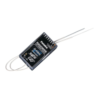
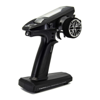
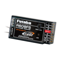
This document describes the Futaba TM-FH 2.4GHz S-FHSS Air System, which includes the TM-FH RF Module and the R2006GS Receiver. This system is designed for use with specific Futaba transmitters (T9C, T9Zwc2, T10C) and operates on the 2.4GHz spread spectrum band.
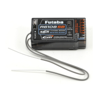
The TM-FH RF Module is a one-way communication transmitter module that replaces the existing module in compatible Futaba transmitters. It utilizes a 2.4GHz Spread Spectrum radio communication system with an exclusive ID code to prevent interference from other S-FHSS systems. The R2006GS receiver is a 6-channel receiver designed to work with the TM-FH module. It features dual antenna diversity (DAD) to ensure optimal signal reception by seamlessly selecting the best signal from two separate antennas. The system also incorporates Fail Safe (F/S) functions for the throttle channel (channel three), including F/S and Battery F/S (B.F/S), which move the throttle servo to a predetermined position in case of signal loss or low receiver battery voltage. The system is factory-linked, but re-linking procedures are provided for new receivers or if desired. A range check feature is included to verify proper operation before flight.
Before installation, ensure the transmitter power is off. Set the transmitter to PPM mode. While not strictly necessary, removing the existing transmitter antenna is suggested as a precaution. Carefully remove the existing module and install the TM-FH module, ensuring not to bend the connector pins.
The strongest signal transmission is from the sides of the TM-FH antenna. Avoid pointing the antenna directly at the model during flight. Do not grasp the antenna during flight, as this can degrade transmission quality.
Install the R2006GS receiver in the aircraft using standard methods, such as wrapping it in foam rubber to protect it from vibration. Ensure both receiver antennas are kept as straight as possible to maximize effective range. Ideally, place the two antennas at 90 degrees to each other, keeping them as far apart as possible. If the model includes metal conductive items, mount the receiver so its antennas exit both sides of the fuselage, at least 1/2 inch away from conductive materials. Avoid bending the coaxial portion or antenna in a tight radius. Do not attach the antenna itself to conductive fuselages. Handle receiver antennas carefully to avoid weakening internal connections. Keep antennas away from motors, ESCs, and other noise sources. Protect the receiver from vibration, shock, temperature extremes, and moisture by wrapping it in a sponge or plastic bag.
The TM-FH module and R2006GS receiver are factory-linked. To re-link or link a new receiver:
The F/S function is available for the throttle channel (channel three) and offers three modes:
When airborne voltage drops below 3.8V, the battery failsafe activates, moving the throttle to a predetermined F/S position. Land immediately. To temporarily reset the failsafe for landing, move the throttle stick to the predetermined position for about 30 seconds of control before it reactivates. Using a 4-cell NiCD or NiMH receiver battery pack is recommended for effective B.F/S.
When using the trainer function, ensure the RF is active after turning on the transmitter before switching to the student's control unit. The host device must display a label stating "Contains Transmitter Module FCC ID: AZPTMFH-24G". A minimum separation distance of 20 cm must be maintained between the antenna of this device and all persons. This transmitter must not be co-located or operating in conjunction with any other antenna or transmitter.
For repair service in the U.S.A., consult the instruction manual first. For further assistance, contact Futaba Service Center via their website, email, phone, or fax. If unable to resolve the issue, pack the system in its original container with a detailed note describing the symptoms, system components, model information, and your contact details, then send it to the authorized Futaba Service Center.