This document is a manual for the Futaba 4/5 Channel Digital Proportional Radio Control System. It provides specifications, charging instructions, and operational details for the transmitter, receiver, and servos, along with pre-flight checks and repair service information.
Function Description
The Futaba 4/5 Channel Digital Proportional Radio Control System is designed for remote control applications, likely for model aircraft, given the mention of aileron, rudder, elevator, and throttle controls, as well as pre-flight checks and engine running. The system uses digital proportional technology, allowing for precise and smooth control of connected servos. It includes a transmitter for user input, a receiver to interpret signals, and servos to execute commands.
Important Technical Specifications
Transmitter (T4 or T5):
- Size: 71/7" x 6" x 23/4" (exclusive of antenna)
- Weight: 3 lbs (including batteries)
- Voltage: 9.6 volts DC
- Pulse Width: 1.5 ms neutral, varied 1 ms for full control.
- Features:
- Modern, lightweight, and easy to hold.
- Control sticks are in a convenient operating position.
- Angled antenna for effective radiation pattern.
- Built-in transformer type battery charger.
- Control stick knobs supplied in two lengths for user preference.
- Maximum transformer output for positive control.
- Output meter.
- Nickel cadmium batteries supplied.
Receiver:
- Size: 2.340" x 0.835" x 1.580"
- Weight: 1.5 oz.
- Voltage: 4.8 volts DC
- Features:
- Automatic Gain Control (AGC) circuit for maximum noise suppression.
- Compact and lightweight.
- Factory tuned and adjusted to the transmitter; no further adjustments required.
- Antenna, one 7-pin plug, and two jacks. The 7-pin plug connects to the receiver battery pack and supplies power to the receiver and servos. Multi-connector jack for rudder, throttle, elevator, auxiliary, and aileron servos.
- Receiver connector has a white dot on one end; for auxiliary (5th) channel, plug servo into this end.
- Highly noise-resistive circuits, but care should be taken to minimize electrical noise.
Servos (S2):
- Size: 2.250" x 1.50" x 0.830"
- Weight: 1.84 oz.
- Voltage: 4.8 volts DC
- Travel Time: 0.6 seconds end to end.
- Thrust: 41 lbs
- Features: Linear action.
Complete Airborne System:
- Components: Receiver, 4 servos, and battery pack including switch and harness.
- Weight: 15 oz (with 500 MAH Nickel Cadmium battery supplied).
- Voltage: 4.8 volts DC.
Usage Features
Charging Instructions:
- The transmitter has a built-in transformer-type nickel cadmium battery charger.
- A dual charging cord is provided, featuring a standard 110-volt 2-prong line cord plug, a seven-pin male connector, and a four-pin female connector.
- Procedure:
- Turn the transmitter switch OFF.
- Turn the receiver switch to the ON position (charging will not occur if the switch is in the wrong position).
- Plug the 4-socket connector into the transmitter.
- Plug the 7-pin male plug into the receiver battery pack.
- Plug the line cord plug into a 110-volt AC household outlet.
- Check the charging indicator light (top right-hand side of the transmitter); when lit, both batteries are charging.
- Charging Time: 18 to 24 hours for a 100% charge, providing approximately 3 hours of operation.
- Initial Charge: Before initial hook-up and operational check, both transmitter and receiver batteries should be charged for 24 hours.
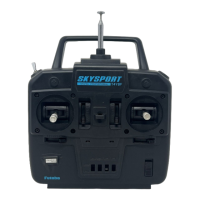
Transmitter Controls (Front Panel):
- Control Sticks: Two control sticks for primary control.
- Trim Levers: Four trim levers for fine-tuning the neutral position of the main controls.
- Auxiliary (5th) Channel Lever: One lever for operating the auxiliary channel, located just below and to the left of the output meter.
- Output Meter: Displays output.
- Top Panel: On-off switch, antenna mount, charging light indicator.
- Bottom Panel: Two thumb screws for accessing the battery compartment.
- Side Panel (Left): Contains battery charging connectors.
- Control Functions:
- Left Control Stick: Operates throttle and aileron.
- Right Control Stick: Operates rudder and elevator.
- Trim Levers:
- Right of left stick: Controls throttle servo idle position.
- Below left stick: Controls aileron trim.
- Left of right stick: Controls neutral position of the servo activated by vertical stick movement (elevator).
- Below right stick: Controls neutral position of the servo activated by horizontal stick movement (rudder).
- The auxiliary or 5th channel is not independently trimmable.
- Control Stick Knobs: Two sets of different lengths are supplied. Knobs can be interchanged by pulling them directly away from the stick and pushing the replacement knob on until fixed.
Receiver Installation:
- The receiver should be loosely mounted in foam rubber or foam plastic to protect against vibration and shock.
- The battery pack should also be protected from vibration by wrapping it in foam rubber.
- The receiver should be protected from fuel by wrapping it in a plastic bag.
- The receiver antenna must be kept as far as possible from other wiring and metal parts.
- Throttle linkage and other metal-to-metal contacts should be made with nylon devices to minimize electrical noise.
Operation Check:
- Connect servo plugs to the receiver jack, then connect the receiver to the battery pack.
- Collapse the transmitter antenna and turn the transmitter switch ON.
- Turn the receiver switch ON. All servos should stop at the neutral position.
- Verify that each servo operates correctly and responds to the individual stick and trim lever.
- Perform this test at least 20 yards from the receiver.
- Do not test for longer than 5 minutes.
- Futaba FP-T4 and FP-T5 are very high-power transmitters.
Pre-Flight Check:
- Perform the final system check with the engine running at a distance of 20-30 yards with the transmitter antenna retracted.
- If the control distance is substantially less with the engine running compared to when it's off, it indicates interference from excessive vibration.
- Once all tests are satisfactory, the system is ready for its first flight.
- If you lack experience with proportional equipment, an experienced flyer should perform the initial flying and trimming of the craft.
Maintenance Features
Repair Service:
To ensure prompt service, follow these instructions:
- Charge batteries for at least 18 hours prior to dispatch.
- Return only the system, separated from your installation. Remove servos from mounts and foam padding from the receiver.
- Plugs or other modifications that interfere with factory testing procedures will be returned to factory standards at your expense.
- Carefully pack all components individually with sufficient packing material to prevent shipping damage. Warranty does not cover components damaged in transit. Insure all packages for protection.
- Include a brief but thorough explanation of all problems and service required, taped to the back of the transmitter. Label servos according to their function.
- Include your full address inside the box and on the outside.
- Include a packing list of all items being returned and double-check to ensure all items are packed.
- Send the gears for repairing back to the distributor or local dealer.