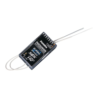
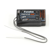
To obtain the best results of the diversity function, please refer
to the following instructions:
WARNING
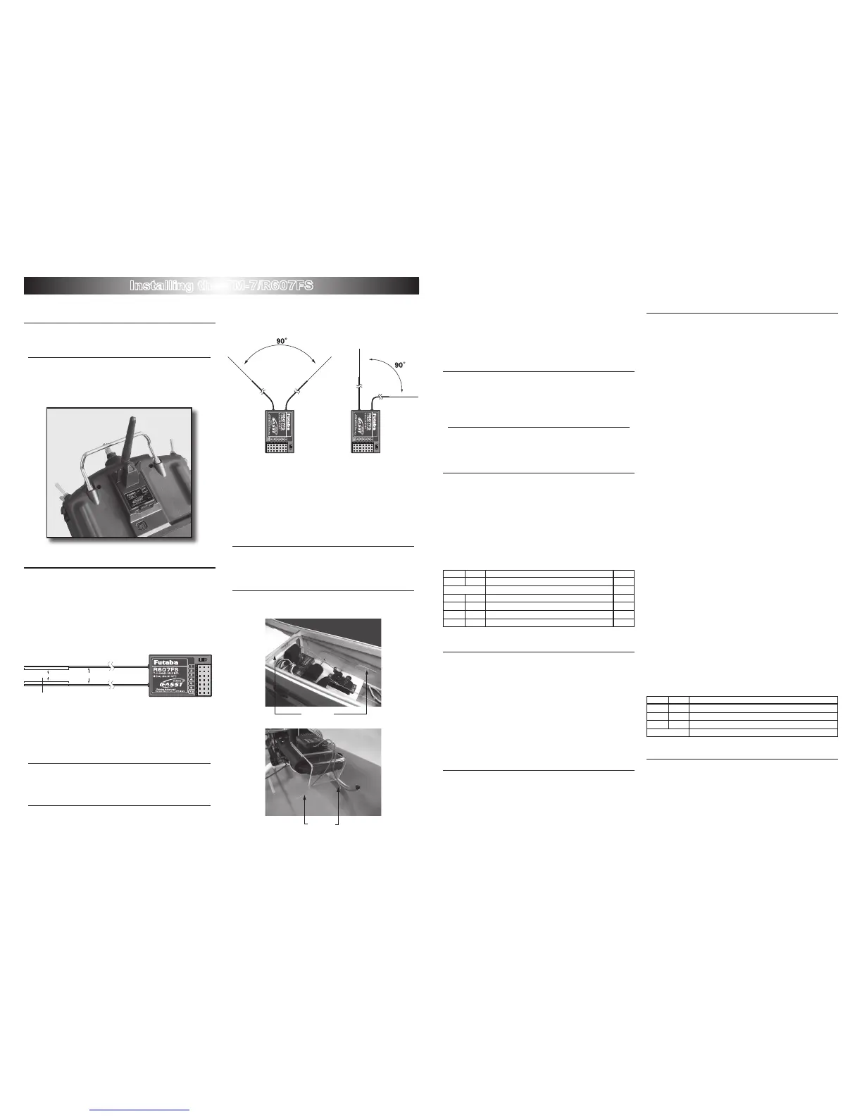
The two antennas must be kept as straight as possible.
* Otherwise it will reduce the effective range.
The two antennas should be placed at 90 degrees to
each other.
Note: This is not a critical figure, but the most important
thing is to keep the antennas away from each
other as much as possible.
Note: Larger models can have large metal objects
that can attenuate the RF signal.In this case
the antennas should be placed at both sides of
the model. Then the best RF signal condition is
obtained at any flying attitude.
The antennas must be kept away from conductive ma-
terials, such as metal and carbon by at least a half inch.
* The coaxial part of the antennas does not need to follow these
guidelines, but do not bend it in a small radius.
Keep the antennas away from the motor, ESC, and
other noise sources as much as possible.
*The main purpose of the photo demonstrates how the antenna
should be placed. For actual installation the receiver must be
wrapped with a sponge or placed with oating material to protect it
from vibration.
* The receiver contains precision electronic parts. It is the most deli
-
cate radio component on-board the model and should be protected
from vibration, shock and temperature extremes.
* If moisture enters the receiver, intermittent operation or a failure
may result. Wrapping the receiver in a plastic bag also protects it
from fuel and exhaust residue which, in some models, can work its
way into the fuselage.
Area select
Normally please set at "GENERAL". In case of in France,
please set at "FRANCE"
WARNING
If using this system in France, always use it to set the
switch to "FRANCE".
* In other countries, both "GENERAL" and "FRANCE" are available.
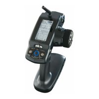
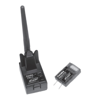
Operation of the TM7
1
Set the transmitter's modulation as "PPM"
Note: When changing from "PCM", the power must be
cycled in order the change to be effective.
LED indication
Green Red Status F/S
solid solid Initializing(When power-up) ---
alternate blink Check RF condition nearby ---
solid off RF power on off
solid blink RF power on(Power downed for ground range check) off
blink off RF power on on
blink blink RF power on(Power downed for ground range check) on
F/S operation
Normally using the F/S function is recommended for safety
reason. In case of, however, not using the F/S, TM-7 can cancel
the F/S operation. In order to change the opertion status, please
follow the procedure shown below;
1
Press and hold the function switch on the TM-7 while
turning on the power.
*The F/S status is changed from previous status. Unless
performing this procedure, the TM-7 keep same status of
the F/S operation.
Battery F/S function
The F/S function also provide the Battery F/S function. When
the voltage of the airborne battery down to approximately
3.8V, the throttle servo move to a predetermined position.
If this happens, you should immediately land! If you need
to increase throttle for your landing approach, you may
temporarily reset the failsafe function by moving the throttle
stick to the predetermined position, after which you’ll have
about 30 seconds of throttle control before the battery function
reactivates.
Link and F/S position setting Pro-
cedure
Each TM-7 has an individually assigned unique ID code. In
order to start operation, the receiver must bind with the TM-
7's ID code. Once the bind is done, the ID code is stored in the
receiver and the re-bind is not necessary unless the receiver
is to be used with another TM-7. (For ight set of TM-7 and
R607FS, the bind is already done at factory. For the reason of
F/S setting that is mentioned below, however, please perform
the linking again to conrm if the F/S operatin is OK.) When
you purchased another R607FS, this procedure is necessary;
otherwise the receiver will not work.
As to F/S position, the throttle position of the transimitter is
stored in the receiver while linking as a F/S position. So please
set the throttle stick at desired F/S position.
1
Place the transmitter and the receiver close to each
other within one (1) meter
2
Turn on the transmitter. (The throttle stick must be
set at desired F/S position)
3
Check the LED that is placed on the TM-7 to see if
the RF signal is active. When the green LED is ON
solid, the RF signal is being sent.
4
Turn on the receiver.
5
Press down the "Easy Link" switch for more than
one second, and release the switch. The receiver
starts the linking operation.
6
When the linking is complete, the LED in the
receiver will change to solid green. Please confirm
that the servos will now operate by your transmitter.
7
Turn off the transmitter and check if the throttle
servo move to the predetermined F/S position.
*Provided that the TM-7's F/S operation status is ON.
8
If the F/S position need to be changed, please
perform the linking procedure again.
Please refer to the table below for the LED status of the
receiver's condition.
Green Red Status
off solid No signal reception
solid off Receiving signals
blink off Receiving signals, but ID is unmatched.
alternate blink Unrecoverable failure (EEPROM, etc.)
Antenna of TM-7
1
The antenna is adjustable so please make sure that
the antenna is never pointed directly at the model
when flying as this creates a weak signal for the receiver.
2
NE V ER gr i p th e anten na whe n flyin g as t his
degrades RF quality.
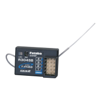
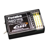
Installing the TM-7/R607FS
Install and adjust the TM-7 module and R607FS receiver as described below.
- 2 - - 3 -
 Loading...