Do you have a question about the FUTABA TM-7 and is the answer not in the manual?
Precautions when using the trainer function to avoid malfunction.
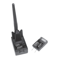
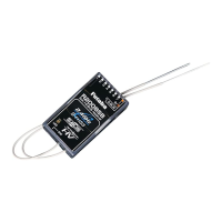
Details the communication system and features of the TM-7 RF module.
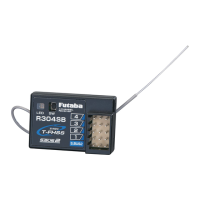
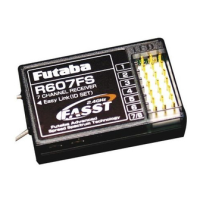
Details power, F/S function, size, and weight of the R607FS receiver.
Instructions for safely attaching the TM-7 RF module to the transmitter.
Guidance on installing the R607FS receiver's antennas for optimal diversity function.
Setting the radio system based on geographical location (e.g., France).
Setting the transmitter's modulation and checking RF signal status.
Procedure for enabling or disabling the Fail Safe function.
Explanation of the Fail Safe function triggered by low airborne battery voltage.
Binding the receiver to the transmitter and setting the F/S throttle position.
Details FCC rules for device operation and potential interference.
Requirements for maintaining safe separation distance from RF radiation.
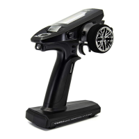
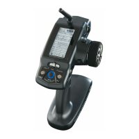
The Futaba TM-7 RF Module and R607FS Receiver constitute a 2.4GHz FASST radio communication system designed for use with Futaba transmitters such as the T7U, T8U, T9C, T9Z, FC-18 Plus, or FC-28. This system offers a robust and reliable connection for remote control applications, particularly in model aircraft, by leveraging spread spectrum technology.
The core function of this system is to provide wireless control over a model. The TM-7 RF Module, when installed in a compatible Futaba transmitter, converts the transmitter's control inputs into 2.4GHz radio signals. These signals are then transmitted to the R607FS Receiver, which is installed in the model. The receiver, in turn, translates these radio signals into servo control signals, allowing for precise manipulation of the model's various functions, such as throttle, ailerons, elevator, and rudder.
A key feature of this system is its 2.4GHz Spread Spectrum radio communication. Unlike older, single-frequency systems, spread spectrum technology distributes the signal across a wider range of frequencies, making it less susceptible to interference and providing a more secure link. The system also incorporates an exclusive ID code, which helps prevent jamming from other FASST systems operating in the vicinity, ensuring that your model responds only to your transmitter.
Safety is enhanced through the inclusion of a Fail Safe (F/S) function, specifically for the throttle channel. This feature allows the user to pre-set a desired throttle position in case of signal loss or low battery voltage. If the receiver loses signal from the transmitter or the airborne battery voltage drops below a critical level (approximately 3.8V), the throttle servo will automatically move to this predetermined safe position. This can prevent runaway models and minimize potential damage. The Battery F/S function provides an additional layer of safety by prompting an immediate landing when the battery voltage is low, though it allows for temporary throttle increase for landing approaches before reactivating the failsafe.
The R607FS Receiver is a 7-channel receiver, capable of controlling up to seven servos. It features a diversity antenna system, which is crucial for maintaining a strong signal in the 2.4GHz band. Since 2.4GHz wavelengths are shorter and more susceptible to signal loss due to obstructions, the diversity antenna system uses two antennas to improve reception reliability by selecting the best signal at any given moment.
Before operation, a crucial step is the "Link and F/S position setting procedure." Each TM-7 module has a unique ID code, and the receiver must be "bound" to this specific ID. This binding process involves placing the transmitter and receiver close to each other, turning on the transmitter with the throttle stick at the desired F/S position, and then activating the "Easy Link" switch on the receiver. Once linked, the receiver stores the ID code, and re-binding is only necessary if the receiver is to be used with a different TM-7 module or if the F/S position needs to be changed. This ensures that the model responds only to its designated transmitter.
A "Range Check" procedure is recommended before each flight. This involves reducing the RF power of the transmitter by pressing and holding the function switch on the TM-7. While in this reduced power mode, the user walks away from the model, operating the controls to confirm proper function at a distance of 30-50 paces. This helps identify any potential issues such as loose servo connections, binding pushrods, or low battery charge before flight. The range check should be performed with the engine off and then with the engine running at various speeds to check for any interference.
The TM-7 RF Module includes an LED indicator that provides visual feedback on its operational status. Different LED patterns (solid green, blinking red, solid red, etc.) indicate various states such as initialization, RF power on, RF power reduced for range check, or issues with RF conditions. This allows the user to quickly assess the module's status.
Antenna installation for the R607FS Receiver is critical for optimal performance. The two diversity antennas should be kept as straight as possible and placed at a 90-degree angle to each other. They must also be kept at least half an inch away from conductive materials like metal and carbon, and away from noise sources such as the motor and ESC. For larger models with significant metal objects, placing antennas on both sides of the model can improve RF signal conditions across different flying attitudes.
The TM-7's antenna is adjustable, but it's important to ensure it's never pointed directly at the model during flight, as this can create a weak signal for the receiver. Additionally, users are cautioned against gripping the transmitter antenna while flying, as this can degrade RF quality and lead to loss of control.
The system also allows for an "Area select" setting, typically set to "GENERAL." However, for users in France, there is a specific "FRANCE" setting that must be used to comply with local regulations.
The manual emphasizes the importance of proper installation and handling to ensure the longevity and reliability of the system. The receiver, containing precision electronic parts, is delicate and should be protected from vibration, shock, and extreme temperatures. Wrapping the receiver in a sponge or floating material is recommended to absorb vibrations. Protection from moisture, fuel, and exhaust residue is also advised, possibly by placing it in a plastic bag, to prevent intermittent operation or failure.
In case of any operational issues, the manual advises users to first re-read the instruction manual and recheck their system. If problems persist, a repair service is available. When requesting repair, users are asked to provide a detailed description of the problem, including when it occurred, the system components involved (transmitter, receiver, servos, model numbers), the model name, and their contact information. This detailed information helps the service center diagnose and address the issue effectively.
The system's design, with its exclusive ID code and fail-safe functions, inherently contributes to its maintenance by preventing common issues that could lead to damage. By ensuring a secure and reliable link, the system reduces the likelihood of crashes caused by interference or signal loss, thereby minimizing the need for repairs due to operational failures. Regular range checks and adherence to antenna installation guidelines are key preventative maintenance steps that users can perform to ensure continued safe and reliable operation.
| Channels | 7 |
|---|---|
| Power Supply | 4.8 - 7.4V |
| Band | 2.4GHz |
| Voltage | 4.8 - 7.4V |
| Voltage Range | 4.8 - 7.4V |
| Compatible Protocols | FASST |