10
Amp’s control connecting
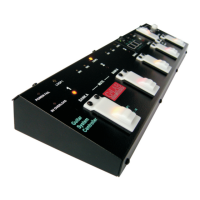
The GSC enables to set the selected amp settings (active channel and/or reverb on/off) by its
footswitch input (or inputs). SW1 to SW4 outputs work on the latching system principle. Majority of amps is
controlled in this way. SW1&2 and SW3&4 outputs’ circuit diagram is shown below. SW1 to SW4 lit
indicators mean short-cutting of the adequate relay’s contacts. Contact a manufacturer or an authorised
service point to check if the particular amp’s model can be controlled in this way.
OUT
SW1&2
or
Sleeve
OUT
SW3&4
Ring
Tip
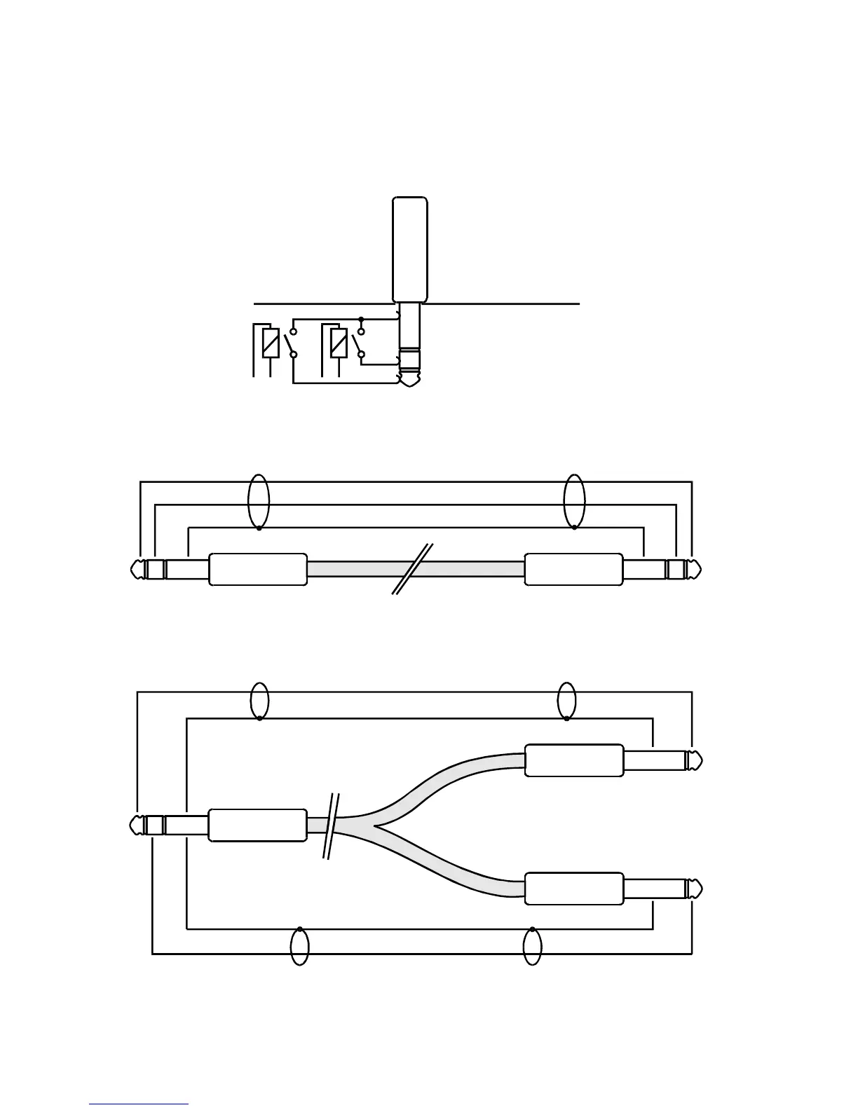
When this way of amp’s control is possible and it is equipped with stereo Jack ¼’ connector (or
connectors) the connection should be done using stereo Jack/Jack cable.
Sleeve
Ring
Tip
When this way of amp’s control is possible and it is equipped with mono Jack ¼’ connector (or connectors)
the connection should be done using Y type cable.
Sleeve Sleeve
SleeveSleeve
Ring
Tip
Tip
Tip