g.tec medical engineering GmbH g.USBamp, USB Biosignal Amplifier: Instruction for use
____________________________________________________________________________________________________________________
V2.16.09
Page 10
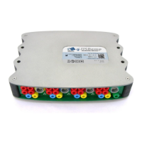
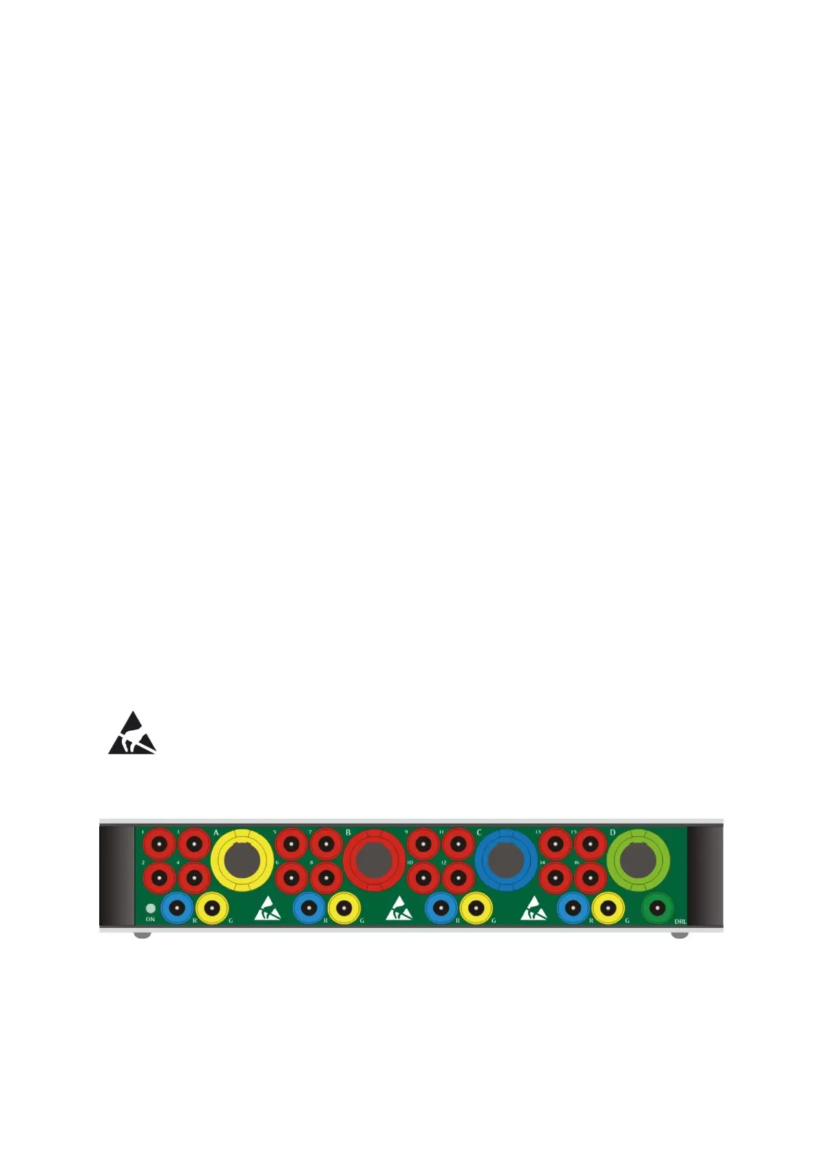
4 Explanation of switches, connectors and LEDs
Sockets, connectors and LED on the front side
g.USBamp has 4 mono-polar amplification groups with separated ground and reference potentials:
Group A:
Safety sockets 1 - 4: 4 analog input channels for EEG
Push-pull connector A is connected to safety sockets 1 - 4
Group B:
Safety sockets 5 - 8: 4 analog input channels for EEG
Push-pull connector B is connected to safety sockets 5 - 8
Group C:
Safety sockets 9 - 12: 4 analog input channels for EEG
Push-pull connector C is connected to safety sockets 9 - 12
Group D:
Safety sockets 13 - 16: 4 analog input channels for EEG
Push-pull connector D is connected to safety sockets 13 - 16
Each group has its own reference socket R and ground socket G. The 4 ground sockets and reference
sockets can be connected. The calibration signals are also available on the push-pull connector on
group D. The DRL socket is for internal testing usage only.
The green LED on the left side (ON) indicates power on.
The electrostatic discharge warning symbol: electrostatic discharge impulses must
be avoided when connecting .electrodes to any of the safety sockets or push pull
connectors. Follow the steps in chapter “Save operation of g.USBamp” to avoid
electrostatic discharge impulses.
g.USBamp front side sockets, connectors and LED