Global-Tek (Singapore) Pte Ltd
Page
6
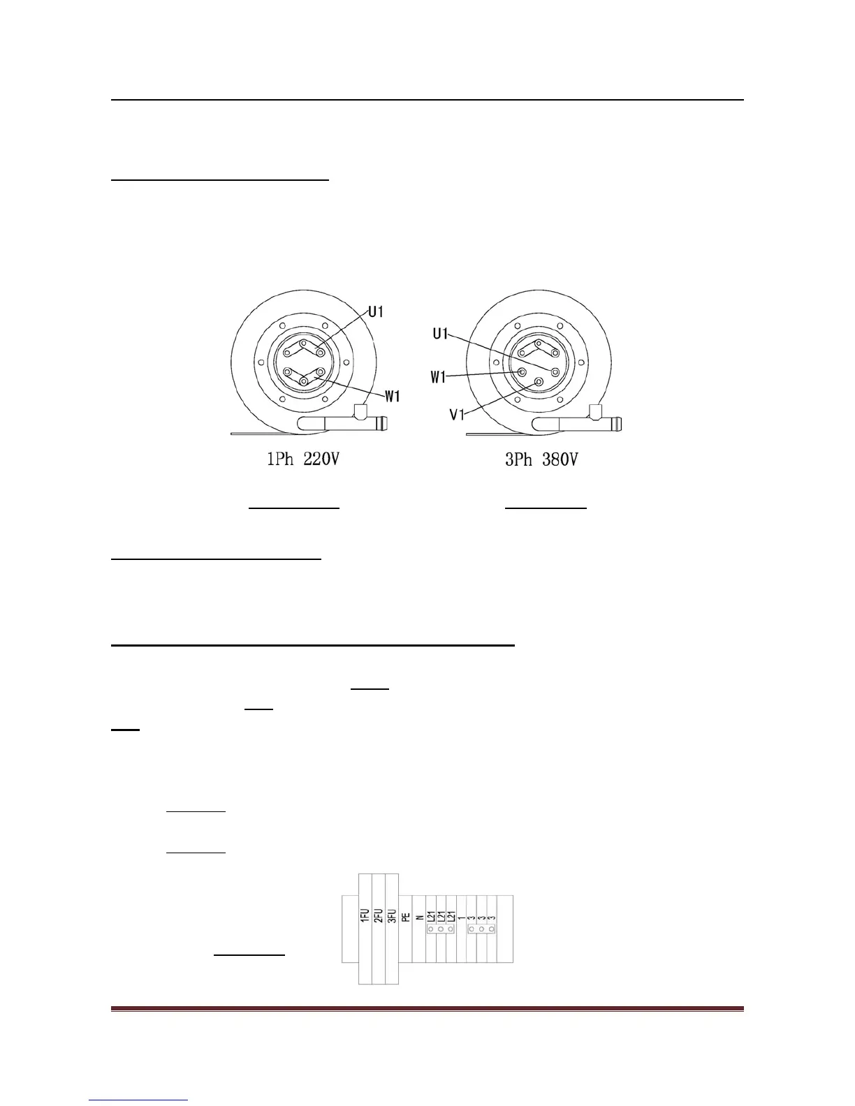
B/ In booster heating element
1/ Remove wire V1 from heating element (diagram 3B),
2/ connect three points together, make it becomes like Diagram 3A,
3/ connect U1 & W1 to each side of the terminals.
Diagram 3A Diagram 3B
C/ In booster heater contactor
Remove wires L2 & V2 from booster heater contactor
Signal terminals for connecting detergent dispenser
In the electrical control box, 1FU provides 220v, 5A constant supplies for dispensing
equipment. Connect 2FU
& N terminals with the detergent signal power of the dispenser, connect
3FU & N terminals with the r inse signal power of the dispenser (see diagram 4), each power
loading must not exceed 3A. During wash cycle, 2FU provides 220V output; during r inse cycle,
3FU provides 220V output. Please refer to the electrical wiring diagram on the machine case.
z Attention
: The pull out distance of the electrical box should be put into consideration for
all the wire connections, to prevent wires from loosening.
z Attention: Please use 600V or above sealed electrical wire, never try telephone wire.
Diagram 4
 Loading...