B
B
X
X
/
/
B
B
X
X
G
G
-
-
1
1
0
0
0
0
0
0
S
S
e
e
r
r
i
i
e
e
s
s
G
G
r
r
o
o
o
o
v
v
e
e
M
M
e
e
a
a
s
s
u
u
r
r
e
e
m
m
e
e
n
n
t
t
G
G
a
a
g
g
e
e
O
O
p
p
e
e
r
r
a
a
t
t
i
i
o
o
n
n
M
M
a
a
n
n
u
u
a
a
l
l
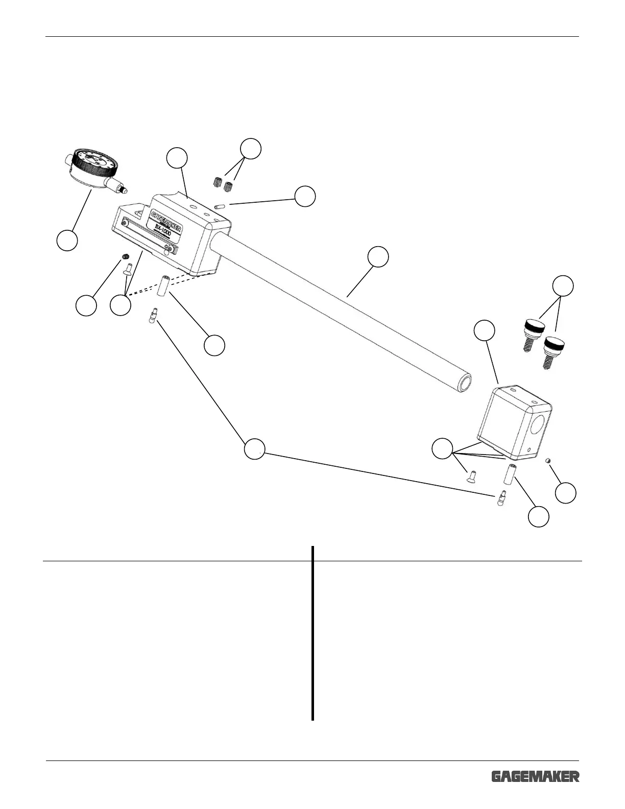
System Components
Take some time to become familiar with all the parts that make up the BX-1000 gages by
reviewing the labeled diagram below. The part names are important for understanding the
operating instructions.
Component List
Item Description Model Qty Item Description Model Qty
1
Upper block assembly
with wear pad
BX-1000-1A
1 7
Contact point adjustment
screw (¼-28 x ¾”)
BX-1000-7A 2
2 Extension rod lock screw
BX-1000-2A
2 8 Contact point lock screw BX-1000-8A 2
3 Indicator set screw
BX-1000-3A
1 9 Indicator 803 or 513SGA 1
4
Lower block assembly
with wear pad
BX-1000-4A 1 10 Contact point T188 2
5 Lock knob
BX-1000-5A
2 11 Extension rod BX-R13 1
6
6-32 X ⅜” Flat head wear
pad screws
BX-1000-6A 8
BX-1000 Model Gage
2