FC66002179 – Rev.00
19
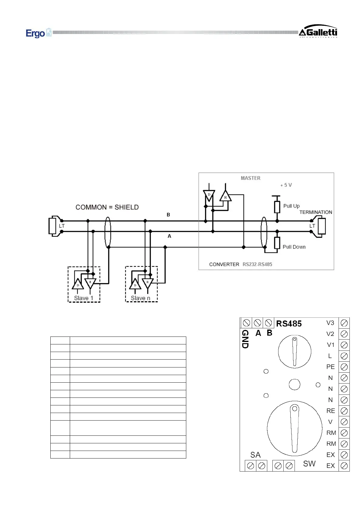
“LARGE” Solution (RS232-RS485 or USB-RS485 converter supplied with the software)
Activate only the termination resistor on the last controller in the network (Jumper J5)
Note: “LARGE” Solution (serial converter without pull-up/pull-down and termination resistors)
Activate the pull-up/pull-down and termination resistors (jumpers J3, J4 and J5) on the controller near the
converter and, as in the previous case, only the termination resistor on the last controller in the network (Jumper
J5)
“SMALL” Solution
Activate the pull-up/pull-down and termination resistors (jumpers J3, J4 and J5) on the master controllers and, as
in the previous case, only the termination resistor on the last controller in the network (Jumper J5)
The network connection scheme entails a simple parallel connection, which must:
(1) Comply with the polarity of the connection: indicated with A(-) and B(+)
(2) Avoid ground loops (ground shield at one end only)
V1 Minimum speed
V2 Medium speed
V3 Maximum speed
L Phase
PE Ground
N Neutral
RE Valve for additional heat exchanger
V Valve for standard heat exchanger
RM Economy contact (Large only)
SW Water temp. sensor
SA Air temp. sensor
EX
External auxiliary contact (230 V=OFF;
contacts open=ON)
A RS485 network negative
B RS485 network positive
GND RS485 network common


 To Next Page