Vers. No. 6.1
116 Released: 25/04/2017
5 Configuration → Configuring analog outputs
Since digital signals do not require any Decimal places, you
can enter 0 here. 1 is sufficient for the Field length. With a
digital input you can also specify a unit (optional).
For several inputs/outputs and the type Status field (Type of
column), as well as the transfer as a number (e.g. as integer),
there is also the type Status field 32 with which all existing
inputs or outputs are transferred as binary numbers. Define a
suitable field length here depending on the number of inputs
and outputs.
When the dialog is closed, the number of transferred places
and the u
nit in the column Format/balance are displayed.
6. Click in the column Range/erro
r to define the reaction in the
case of an error for the digital outputs (optional).
7. Save the changes in a file and close the module once you have
made all the changes:
or File > Save to file and finish.
The file is created within the project folder and the file name
is genera
ted automatically. The project folder bears the same
name as the project. The generated file name contains the
address of the Test Controller through which the module is
connected and an identifier for the relevant module.
If the modules are connected through a Test Controller, new
module settings must also be updated there. Select
or File
> Write project (update) in
the test.commander. The project
file is in this case automatically updated.
5.5 Configuring analog outputs
In order to set parameters you should be connected to the mod-
ule and have called the configuration program (ICP 1
00 which is
started automatically by test.commander):
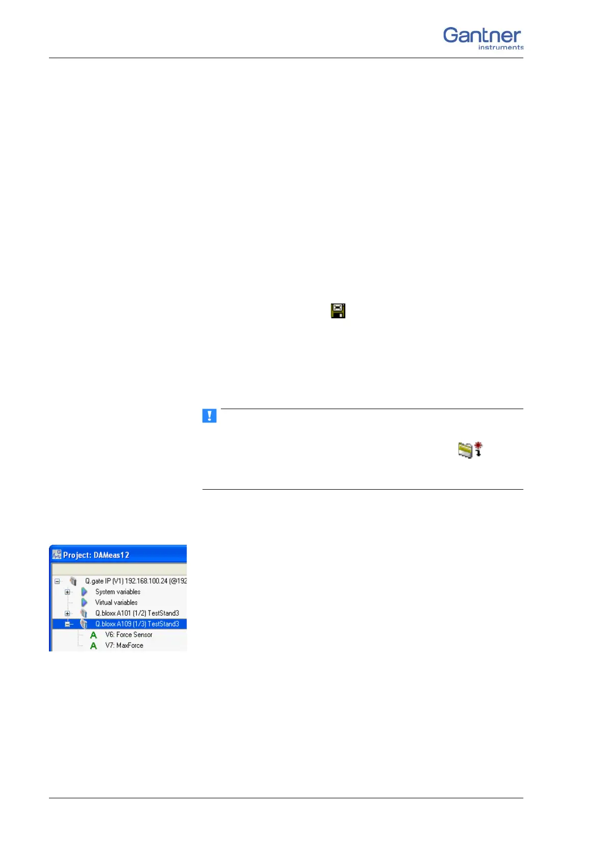
Mark a module and
select Configuration from the context menu or double
click on a
module or module signal (variable) to start the configuration pro-
gram. Then carry out all the module settings in the window of this
program.
You can however also configure a project without a direct con-
nection and then, once you have established the connection, load
the correspondi
ng files into the modules and load Test Controller.
All module signals are defined as variables. Therefore, for the
entry acti
vate the tab Variable definition in the configuration
program.
 Loading...