12
9) Pull chain bar forward until chain is snug in chain bar
groove. Ensure all drive links are in the bar groove.
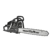
10) Now, fit the metal spacer to the bar bolts, install
clutch cover (22) making sure the adjusting pin
(
2
) is positioned in the lower hole (
3
) in the chain
bar. Remember this pin moves the bar forward and
backward as the screw is turned. (Fig. G)
11) Install the chain bar locking nuts(8) and tighten with
Chain adjustment & Spark plug tool (19) only. Tension
the chain as detailed in the next section. (Fig. H)
2. CHAIN TENSION
WARNING: Wear protective gloves when
handling chain. The chain is sharp and can
cut you even when it is not moving.
NOTE: When adjusting chain tension, make sure the
chain brake nuts are finger tight only. Attempting to
tension the chain when the chain brake nuts are tight
can cause damage.
Checking the tension:
Use the end of the Chain adjustment & Spark plug tool
(19) to move the chain(24) around guide bar(12) (Fig. I).
If the chain is too tight, it will not rotate around the
guide bar.
If the chain is too loose, it will sag below the guide bar.
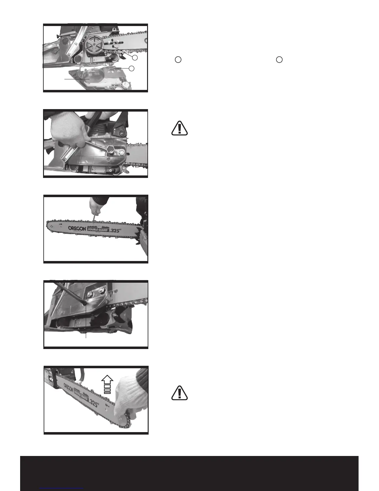
Adjusting the tension (Fig. J):
Chain tension is very important. Chain stretch occurs
during use. This is especially true during the first
few times you use your saw. Always check chain
tension each time you use and refuel your saw.
1) Loosen chain bar locking nuts (8) until they are finger
tight against the clutch cover.
2) Turn chain adjusting screw (9) clockwise until chain
solidly contacts bottom of guide bar rail.
3) Using the Chain adjustment & Spark plug tool (19),
roll chain around guide bar to ensure all links are in bar
groove.
4) Lift up tip of guide bar to check for sag. Release
tip of guide bar, then turn adjusting screw clockwise.
Repeat until sag does not exist.
5) While lifting tip of guide bar, tighten chain bar
locking nuts (8) securely with the Chain adjustment &
Spark plug tool (19). (Fig K)
WARNING: DO NOT OVER TIGHTEN!