Do you have a question about the Gardner Denver GD PILOT TS and is the answer not in the manual?
Provides information on manual content, symbols, and version validity.
Outlines requirements for personnel working with the machine for safety.
Specifies the controller's intended application with Gardner Denver D range compressors.
Warns about the risk of electric shock from charged capacitors and safety precautions.
Provides general operating safety guidelines and emphasizes reading all manual sections.
Details specific safety instructions, symbols, and liability disclaimers.
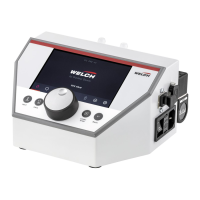
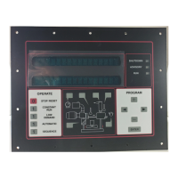
Introduces the GD Pilot TS controller and its scope in EnviroAire compressors.
Explains the controller's functions in managing compressor operation and monitoring.
Describes how to navigate between different display pages using touchscreen tabs.
Details the normal operating display screen, its components, and automatic reversion.
Explains the icons and symbols displayed on the Home page for status indication.
Provides instructions and cautions for cleaning the touch screen safely.
Lists and explains various status messages, including warnings, faults, and operational states.
Explains the procedure and code for locking/unlocking user settings to prevent unauthorized changes.
Describes how to select the display language for the GD Pilot TS controller.
Details the steps to set the current date and time for accurate operation and logging.
Guides users on how to select preferred units for temperature, pressure, and volume flow.
Explains the concept of pressure bands (p1 and p2) and their function in compressor operation.
Describes pressure settings (cut-out, target) for variable speed compressor models.
Describes pressure settings (cut-out, cut-in) for fixed speed compressor models.
Provides step-by-step instructions for setting the primary pressure band (p1) parameters.
Details the procedure for setting the alternative pressure band (p2) parameters.
Introduces the Trends tab for monitoring compressor performance over time.
Explains the format and scaling of typical trend graphs for key operational parameters.
Shows how to view operating hours at different volume flows for VS models.
Shows total and on-load hours for FS models and average volume flow.
Describes the weekly profile graph for analyzing average volume flow over an 8-day period.
Explains how to access various submenus for configuration and settings.
Describes how to view and reset maintenance and operational hour meters.
Details the options available in the Control menu for adjusting operational parameters.
Explains the Timer Control menu functions for scheduling compressor start/stop times.
Describes how to configure programmable inputs and outputs for external devices.
Details settings for RS485 communication parameters.
Covers settings for language, units, and rated delivery volumes.
Explains access to factory-programmed settings that cannot be user-changed.
Mentions the SD card function for data recording and maintenance assistance.
Describes the Water Circuit Control menu for managing water change cycles.
Explains how to access and view a list of the last 64 faults and warnings.
Details the use of the Access Code tab for security and menu access.
Provides a graphical overview of the GD Pilot TS controller's menu system.
Instructs on how to use the emergency stop button for immediate machine shutdown.
Explains the process of starting the compressor, including prerequisites and display indicators.
Lists conditions that prevent the compressor from starting automatically.
Explains how the controller maintains line pressure by adjusting motor speed.
Covers the two operating modes (Automatic, Continuous) and their characteristics.
Describes the automatic and cyclical water change functions for maintaining water quality.
Details the standard procedure for stopping the compressor via the stop button.
Explains how the system handles warnings, faults, and power failures, including machine behavior.
Provides a checklist of potential causes for faults and warnings to aid troubleshooting.
Explains the format and division of fault and warning codes for compressor and VSD errors.
Introduces tables detailing possible faults, warnings, causes, and remedies.
Lists VSD-related fault numbers, their causes, and remedies for troubleshooting.
Lists compressor-related fault numbers, their causes, and remedies for troubleshooting.
Lists VSD-related fault numbers (E500-E531), their causes, and remedies.
Lists compressor-related warning numbers, their causes, and remedies.
Lists VSD-related warning numbers, their causes, and remedies.
Covers miscellaneous faults, warnings, and operational issues not categorized elsewhere.
Explains how to assign functions to programmable inputs for monitoring and control.
Lists timing and other conditions required for programmable inputs to trigger events.
Describes how to configure programmable outputs for activating external devices or signals.
Explains how to program automatic start and stop times for the compressor.
Provides an example scenario for setting up a 2-shift system using timer control.
Details the process of setting specific start and stop times for multiple timer channels.
Explains how to activate the configured timer control functions within the system settings.
Guides on setting timers specifically for activating the p2 pressure band.
Describes the final step to enable timer control for the p2 pressure band.
Allows programming a delay for the dryer to start before the compressor.
Covers configuration of RS485 serial communication settings for external connectivity.
Explains how to configure automatic restart after a power interruption.
Details how to enable and use the remote start/stop functionality for the compressor.
Describes how to remotely control compressor loading/unloading states.
Explains how to identify and obtain the necessary setup code and reference number.
Guides the user through entering the setup code and compressor data for a replacement controller.
Differentiates between User Level and Maintenance Level access for parameter changes.
Explains how to unlock and lock the maintenance level using access codes.
Lists extra graphs and parameters available only at the maintenance level.
Details how to reset the on-load hour statistics for performance tracking.
Guides on resetting the service interval indicator when maintenance is performed.
Explains how to set or limit the compressor's rated pressure for safety or network compatibility.
Describes settings for water change cycles and home page indicators.
Covers the use of the SD card for data logging and monitoring compressor performance.
Explains how recorded data files (settings and data files) are named and structured.
Specifies requirements for SD card compatibility and formatting for the data recorder.
Introduces Base Load Sequencing and its two main functions for compressor group control.
Outlines the need for a communication module (RS485:3) for BLS master functionality.
Explains how the GD Pilot TS acts as a master device for controlling up to 3 slave compressors.
Lists compatible electronic slave controllers and required software versions for BLS.
Provides a detailed table of supported controllers and their minimum software versions.
Explains how to activate and access the BLS feature and its initial setup.
Lists and explains status messages displayed for compressors within a BLS group.
Guides on accessing and configuring individual compressor settings within the BLS group.
Presents a graphical overview of the menu hierarchy for Base Load Sequencing.
Explains how to access and adjust BLS settings including On/Off, Setpoints, Behaviour, Configuration, and Timer Control.
Explains the control algorithm and how BLS manages compressor groups.
Describes how the BLS sequence is re-established based on compressor operating hours.
Mentions additional trend and statistic graphs available for BLS groups.
Details the process of installing and activating the RS485:3 module for BLS functionality.
Provides a circuit diagram illustrating the wiring for BLS communication between master and slave units.
Guides on configuring communication parameters for slave compressor controllers to work with BLS.
Explains the installation and purpose of the Compressor Module (STD) for connecting non-GD Pilot compressors.
Details how to set the address for the Compressor Module (STD) using DIP switches.
Lists the terminal designations and functions for the Compressor Module (STD).
| Brand | Gardner Denver |
|---|---|
| Model | GD PILOT TS |
| Category | Controller |
| Language | English |