EasyManua.ls Logo

Gardner Denver GD PILOT TS Series - User Manual

Gardner Denver GD PILOT TS Series
80 pages
Print Icon
To Next Page IconTo Next Page
Loading...
USA
ZS1133369 / 00 - January 2015
Translation of the original operating
instructions
Compressor control
GD PILOT TS / L series

Table of Contents

Questions and Answers

  • D
    Denise Duran DVMSep 17, 2025
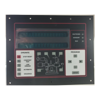
    What does error E504 mean on my Gardner Denver GD PILOT TS Controller?
    • J
      jimmythomasSep 18, 2025
      E504 on your Gardner Denver Controller indicates that communication with the frequency converter is interrupted, and the frequency converter does not respond. Check the main circuit protector (only for compressors with PowerFlex 400 converters) and the ModBus interface wiring.
  • C
    Colleen MorganAug 25, 2025
    Why is my Gardner Denver Controller showing a discharge over pressure?
    • S
      Sandra RichardsonAug 25, 2025
      A discharge over pressure error on your Gardner Denver Controller can be due to several reasons: * Operating pressure exceeded at 1.5 bar / 21 psi. * Pressure losses in the system are too high, which needs correction. * Nominal line pressure values are too high, so check remote-load / idle switching points. * External pressure demand is too high. * The suction regulator may not be closing. * The pressure sensor B1 or B2 could be defective, causing an incorrect display. In this case, check and replace if necessary.
  • E
    Elizabeth WalkerAug 25, 2025
    How to fix high motor temperature M1 on Gardner Denver Controller?
    • J
      James SmithAug 26, 2025
      A high motor temperature (M1) on your Gardner Denver Controller can occur for several reasons. It may be due to the drive motor being started too often, so limit the number of starts and stops. Insufficient cooling of the drive motor could also be a cause, so check the cooling air supply and improve it if necessary. Other potential causes include current draw being too high, a defective power supply, or a defective drive motor. Check the drive motor and replace if needed.
  • G
    Greg LoganAug 27, 2025
    What causes a power supply failure on a Gardner Denver GD PILOT TS Controller and how to fix it?
    • T
      trevinokarenAug 27, 2025
      A power supply failure on your Gardner Denver Controller can stem from several causes, including a power failure, voltage drop, damaged cables or wiring, or loose terminals. Check the cables and wiring, repairing them if needed. Also, check all connection terminals and plugs for secure seating and tighten if necessary.
  • S
    Shane WoodardSep 18, 2025
    What to do if the VSD stop is pressed on my Gardner Denver GD PILOT TS Controller?
    • M
      Michael BanksSep 18, 2025
      If the red stop button on the frequency converter has been pressed while the compressor was running, always switch off the compressor using the GD Pilot TS.
  • W
    Wayne BeardSep 23, 2025
    What does error E506 mean on my Gardner Denver GD PILOT TS?
    • J
      jessicageorgeSep 23, 2025
      E506 on your Gardner Denver Controller (only for compressors with PowerFlex 75x converter) indicates that while the GD Pilot TS has detected that an emergency stop button has been pressed, no corresponding feedback has been received from the converter. Check the Emergency Stop circuit.
  • A
    Amy RodriguezSep 9, 2025
    What does it mean when my Gardner Denver Controller displays Fault VSD F064?
    • C
      Christina StewartSep 9, 2025
      Fault VSD F064 on your Gardner Denver Controller indicates an overload of the frequency converter. Check the differential pressure of the fine precipitator, the oil level, and the water content of the oil.
  • J
    Jacob GarciaSep 10, 2025
    What does error E403 on my Gardner Denver GD PILOT TS Controller mean?
    • M
      Mr. James SloanSep 10, 2025
      E403 on your Gardner Denver Controller means that the compressor outlet temperature has been exceeded.
  • D
    Devon RiosSep 3, 2025
    What to do if my Gardner Denver GD PILOT TS Controller shows a hardware error?
    • T
      toni36Sep 3, 2025
      If your Gardner Denver Controller displays a hardware error, it indicates a hardware error at the controller. Replace the Delcos controller.
  • M
    matthew20Sep 1, 2025
    What should I do if my Gardner Denver GD PILOT TS reports an issue with discharge temperature sensor R2?
    • A
      Ashley GriffinSep 1, 2025
      If your Gardner Denver Controller reports an issue with discharge temperature sensor R2, it may be due to a defective compressor outlet temperature sensor, a general pressure or temperature sensor defect, or faulty sensor wiring. Check and replace the sensor wiring if necessary. Also, check the pressure sensor and/or temperature sensor and replace if necessary.

Summary

1 Foreword

1.1 About These Operating Instructions

Details the scope and content of these operating instructions for compressor controllers.

1.2 Intended Use

Specifies the intended application of the GD PILOT TS controller with L Series compressors.

1.3 Foreseeable Misuse

Defines actions that constitute misuse and require Gardner Denver approval.

1.4 Service and Contact Information

Provides guidance on contacting Gardner Denver for assistance and spare parts, and entering representative details.

2 Safety Requirements

2.1 Labeling of Safety Instructions

Explains the structure and purpose of alert words, hazard descriptions, and protective measures in safety notices.

2.2 Safety Symbols and Usage

Details safety symbols, their meanings, and required user behavior for hazard avoidance.

3 Control Panel and Controller

3.1 General Operation and Parameter Entry

Describes how to navigate input menus and enter parameters, noting their self-explanatory nature.

About the Compressor Controller

Outlines the responsibilities of the compressor controller, including starting, stopping, monitoring, and data entry.

Access Code Input

Details the process for entering access codes to enable specific functions or settings.

4 Controller Menus

4.1 Menu Structure Overview

Provides a graphical representation of the controller's menu system, outlining available sections and functions.

4.2 The Home Menu

Details the 'Home' screen components, status indicators, and pressure band information.

4.3 Pictogram and Menu Tabs

Explains the pictogram display and introduces the main menu tabs for navigation.

4.4 Trends Menu

Introduces the 'Trends' menu for monitoring compressor performance via various charts.

4.5 Settings Menu

Describes the 'Settings' menu for individually adjusting operating parameters and configurations.

4.6 Fault History Menu

Covers the 'Fault History' menu for reviewing alarms and the procedure for acknowledging them.

4.7 Access Code Menu

Explains how to use the 'Access Code' menu to enable special operating functions.

5 Configuration

5.1 Choose Language

Guides the user through selecting the display language for the controller interface.

5.2 Set the Date and Time

Details the procedure for setting the current date and time on the compressor controller.

5.3 Setting Units of Measure

Explains how to set temperature, pressure, and volume flow units for display.

5.4 Additional Settings

Covers advanced settings for compressor operation, including pressure bands and I/O configuration.

5.4.1 Setting Pressure Bands (p1, p2)

Details configuration of two pressure bands for compressors with speed control (RS) and fixed speed (FS).

5.4.2 Programmable Inputs and Outputs

Explains configuration of programmable inputs and outputs for monitoring and control functions.

5.4.3 Timer Control

Enables automatic compressor operation based on programmed time schedules and pressure bands.

5.4.4 Dryer Pre-Run Time Programming

Sets a pre-run time for the dryer to optimize compressor start-up conditions.

5.4.5 RS485 Communication Setup

Configures RS485 communication parameters for external device connectivity and monitoring.

5.4.6 Automatic Restart After Power Loss

Configures automatic restart capability and maximum allowable downtime after power interruptions.

5.4.7 Setting Remote Start;Stop

Explains how to configure remote start/stop functionality and set start-up delays for compressors.

5.4.8 Remote On-Load and Off-Load (FS)

Details how to enable remote control of On-Load/Off-Load switching for FS compressors.

6 Operating Procedures

6.1 Emergency Stop and Basic Operation

Covers emergency shutdown, normal compressor start-up, and factors inhibiting start.

6.4 Compressor Operation Modes

Explains speed control, load management, and the two operating modes: Automatic and Continuous.

6.6 Stopping and Monitoring Operation

Details how to stop the compressor and monitor its operational status, warnings, and faults.

7 Fault Clearing and Troubleshooting

7.1 Fault Clearing Checklist and Codes

Provides a checklist for fault prevention and explains the structure of fault and warning codes.

7.3 Troubleshooting Common Faults

Details faults from frequency converters and compressors, including causes and remedies.

7.3 Troubleshooting Warnings and Other Faults

Lists compressor warnings, frequency converter warnings, and other fault conditions with solutions.

8 Additional Controls

8.1 Maintenance Level Access

Details enabling the maintenance level to modify parameters and access advanced features.

8.2 Maintenance-Level Trend Charts

Lists additional trend charts like VSD Heatsink Temperature and Output Current available at maintenance level.

8.3 Statistics Reset and Service Interval

Covers resetting on-load hour statistics and setting the next service interval.

8.4 Data Recording with SD Card

Explains starting, stopping, and managing data recording to an SD card.

9 Setting Up a Replacement Controller

9.1 Setup Code and Compressor Reference Number

Details the critical setup code and reference number required for correct compressor configuration.

9.2 Controller Replacement and Initial Setup

Guides on language selection, entering codes, and initial setup for a new controller.

Emergency Stop Function Test

Describes testing the emergency stop input for VSD and controller functionality.

10 Base Load Sequencing (BLS)

10.1 BLS Overview and Supported Systems

Introduces BLS, supported configurations, slave controllers, and basic system requirements.

10.2 Supported Slave Controllers

Lists compatible electronic controllers and required software versions for slave units in a BLS group.

10.3 Activating and Deactivating BLS

Details the procedure for enabling and disabling the Base Load Sequencing function via access code.

10.4 Compressor Status Messages

Lists and explains various status messages displayed for compressors within a BLS group.

10.5 Compressor Settings and Information

Explains how to access and modify settings and view information for individual compressors in a BLS group.

10.6 BLS Settings: Configuration, Setpoints, and Behavior

Details configuration of BLS, setpoints like pressure bands, and operational behavior settings.

10.8 Trend and History Charts for BLS

Lists additional trend charts available when BLS is active, such as Volume Flow (BLS).

10.9 RS485:3 Module Installation and Wiring

Provides instructions for installing the RS485:3 module, slave communication setup, and wiring.

10.10 Compressor Module (STD) Installation and Configuration

Details STD module installation, address setting, digital I/O functions, and wiring examples.

Setting the Address of the STD Module

Details setting the DIP switches to configure the address for the STD compressor module.

STD Module Digital Inputs

Explains the function and connection of digital inputs for the STD module, including 'Operating' and 'Motor' inputs.

STD Module Digital Outputs

Describes the function and connection of digital outputs from the STD module for controlling compressor functions.

STD Module Connection Assignments and Examples

Provides wiring examples and connection assignments for the STD module's digital inputs and outputs.

11 Appendix

11.1 Status Messages

Provides a comprehensive list and explanation of all status messages displayed by the controller.

11.2 Settings Recording Tables

Contains tables for recording compressor data and set values from various controller menus.

Gardner Denver GD PILOT TS Series Specifications

General IconGeneral
SeriesGD PILOT TS
Input Voltage24V DC
Protection ClassIP54
Operating Temperature-20°C to 60°C
Communication InterfaceModbus RTU

Related product manuals