Do you have a question about the Gardner Denver AirSmart VS25A and is the answer not in the manual?
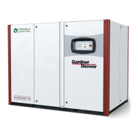
Explains the process of air compression using meshing helical rotors and volume reduction.
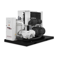
Provides guidance on proper methods for lifting and transporting the compressor package safely.
Details essential checks and servicing required before operating a new compressor unit.
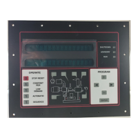
Describes the AirSmart controller, its functions, integration, and operator interface.
Specifies the factory-fill lubricant (AEON 9000SP) and recommends regular oil analysis.
Explains the function and maintenance of air-cooled radiator-type heat exchangers and their cooling fans.
Guides on how to inspect, clean, or replace the air filter element for optimal performance.
Details procedures for inspecting and replacing the coupling element between the motor and compressor.
Outlines the inspection process for the minimum pressure check valve to ensure proper function and sealing.
Describes how to inspect the inlet control valve for wear and tear on its seals during pressurized conditions.
Explains how to test the pressure relief valve annually for proper operation without user-serviceable parts.
Describes how to inspect ventilation filter elements to ensure peak electronic efficiency and prevent temperature-related stoppages.
Provides guidelines for grease quality and regreasing intervals for electric motor ball bearings based on service type.
Lists daily checks including air filter, oil separator, oil level, and operational parameters verification.
Identifies possible causes and remedies for the compressor failing to initiate operation, including checks for disconnects and fuses.
| Brand | Gardner Denver |
|---|---|
| Model | AirSmart VS25A |
| Category | Controller |
| Language | English |