Do you have a question about the Gardner Denver AIRSMART and is the answer not in the manual?
Indicates a hazard with medium risk, potentially fatal if not avoided.
Indicates a hazard with low risk, potentially minor injury if not avoided.
Indicates a hazard with high risk, potentially fatal if not avoided.
Overview of the AirSmart Controller's capabilities and technical specifications.
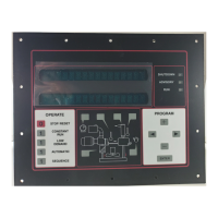
Details about the AirSmart Controller's display, buttons, and status indicators.
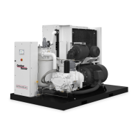
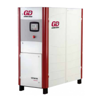
Description of the physical layout and components of the compressor's front panel.
Explanation of the information displayed on each of the four lines of the controller's screen.
Explanation of the function of each LED indicator on the control panel.
Details on the purpose and operation of each button on the controller's keypad.
Step-by-step instructions for configuring the primary operating pressure set point.
Guide on how to adjust the pressure points for compressor loading and unloading.
Explanation of how the AirSmart controller manages variable speed compressor operation.
Description of control logic for compressors using variable flow mechanisms.
How the AirSmart controller operates fixed speed compressor models.
Accessing and adjusting operational parameters like pressure and mode.
Viewing maintenance timers, total hours, and other operational status information.
Monitoring various pressure and temperature readings from the compressor.
Displaying current status of motors, including current, voltage, and speed.
Information related to Variable Frequency Drives (VFDs) controlling compressor motors.
Reviewing past advisory faults and system status at the time of occurrence.
Accessing records of the last six shutdown faults and associated system status.
Viewing calculated parameters used for compressor control and system diagnostics.
Accessing compressor status information and operational parameters.
Configuring basic compressor operations like language, pressure, and mode.
Resetting maintenance timers and viewing total operating cost.
Setting up compressor sequencing operations, visible with Communications Module.
Advanced configuration parameters requiring a password for access and modification.
Adjusting the real-time clock functions of the compressor.
Setting compressor model, voltage, elevation, and other configuration parameters.
Functions reducing compressor speed to prevent nuisance shutdowns in extreme conditions.
Alerts for needed service or parameters approaching shutdown levels.
Protection from component failure or extreme conditions, requiring reset after stop.
Mapping input/output functions to specific ports and devices.
Lists available digital inputs and outputs for compressor control and monitoring.
Lists available analog inputs and outputs for compressor sensing and control.
Procedure for programming a "RUN" output signal on the controller.
Physical dimensions and mounting arrangement for the All-In-One controller unit.
Physical dimensions and mounting arrangement for the Full-Sized controller.
UL recognition status for the AirSmart Controller in US and Canada.
Operating and storage temperature, humidity specifications for the controller.
Power input, digital/analog I/O specifications, and relay output ratings.
Requirements for connecting a main motor starter remotely mounted from the compressor.
Requirements for connecting a starter for a remotely mounted air-cooled cooling module.
| Brand | Gardner Denver |
|---|---|
| Model | AIRSMART |
| Category | Controller |
| Language | English |