G
Greg LoganAug 27, 2025
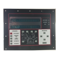
What causes a power supply failure on a Gardner Denver GD PILOT TS Controller and how to fix it?
- TtrevinokarenAug 27, 2025
A power supply failure on your Gardner Denver Controller can stem from several causes, including a power failure, voltage drop, damaged cables or wiring, or loose terminals. Check the cables and wiring, repairing them if needed. Also, check all connection terminals and plugs for secure seating and tighten if necessary.