13-8-638 Page vii
LIST OF ILLUSTRATIONS
Figure 1-1 – Compressor Cycle....................................................................................................................1
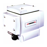
Figure 1-2 – Compressor Illustration.............................................................................................................2
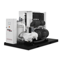
Figure 2-1 – Typical Compressor Room.......................................................................................................8
Figure 2-2 – Air Flow Chart...........................................................................................................................8
Figure 2-3 – Cold Weather Installation .........................................................................................................9
Figure 4-1 – Control Schematic ..................................................................................................................17
Figure 4-2 – Key Pad ..................................................................................................................................18
Figure 4-3 – Wiring Diagram – Full Voltage................................................................................................22
Figure 4-4 – Wiring Diagram – Full Voltage................................................................................................23
Figure 5-1 – Flow Diagram..........................................................................................................................24
Figure 5-2 – Approximate Oil System Capacities.......................................................................................26
Figure 5-3 – Oil Change Interval.................................................................................................................26
Figure 5-4 – Oil Level Gauge, Oil Fill and Oil Drain....................................................................................30
Figure 5-5 – Oil Filter ..................................................................................................................................31
Figure 6-1 – Air Filter ..................................................................................................................................35
Figure 7-1 – Belt Tension – 3VX Belts........................................................................................................39