Part #1382606 Rev 2 (12/07)Page 10
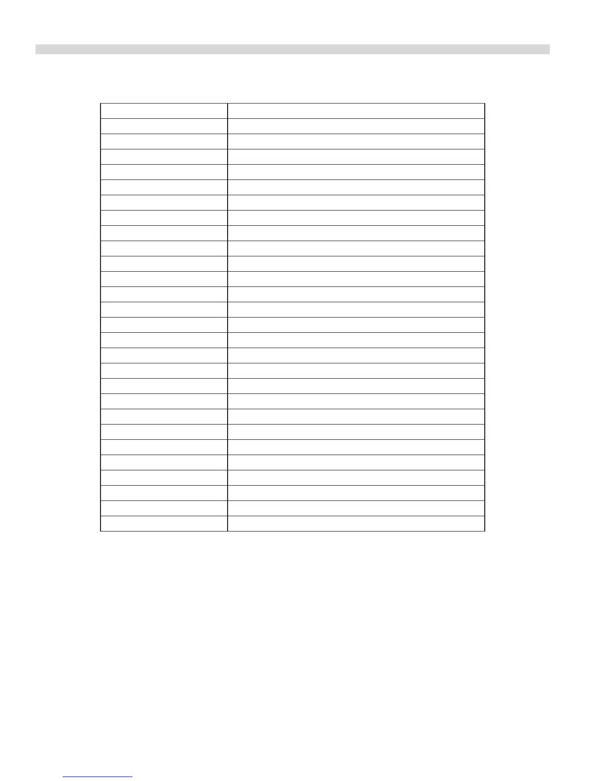
PARTS LIST
PART NUMBER DESCRIPTION
1578600 Switch, Drain Valve
1576400 Drain Valve 1/4 In.
1581200 Micro Switch Bracket
1580900 Clamp, Drain Tube
8003123 Screw, Clamp
8001204 Nut, clamp
1573800 Handle, Return Valve
1581300 Power Shower Single Vat
1578100 Valve, Oil Return
1578600 Micro Switch, Pump control
1578800 Switch, Heater On-O
1029501 Power Cord
1579800 Filter Paper
1579900 Filter Powder
1579699 Filter complete
1574600 Contact Block Assy. w/Heater Contacts At Rear of Pan
1576200 Slip Fitting
1574000 Handle Drain Pan
1579200 Terminal block 12 Pin
1579300 Terminal block 16 Pin
1578300 Transformer, 120/24V
1578400 Relay, Pump Control
1578700 Pump & Motor 120V 60 HZ Viking
1580000 Motor vibration Mounts
1578500 Solenoid Vent Valve
1576300 Slip tting
1578200 O Ring, Slip Fitting
 Loading...