EasyManua.ls Logo

Garmin ECHOMAP ULTRA 126s - User Manual

Garmin ECHOMAP ULTRA 126s
12 pages
Print Icon
To Next Page IconTo Next Page
Loading...
ECHOMAP
ULTRA
INSTALLATION INSTRUCTIONS
Important Safety Information
WARNING
Failure to follow these warnings, cautions, and notices could result in personal injury, damage to the vessel or
device, or poor product performance.
See the Important Safety and Product Information guide in the product box for product warnings and other
important information.
When connecting the power cable, do not remove the in-line fuse holder. To prevent the possibility of injury or
product damage caused by fire or overheating, the appropriate fuse must be in place as indicated in the product
specifications. Connecting the power cable without the appropriate fuse in place voids the product warranty.
CAUTION
To avoid possible personal injury, always wear safety goggles, ear protection, and a dust mask when drilling,
cutting, or sanding.
To avoid possible personal injury or damage to the device and vessel, disconnect the vessel's power supply
before beginning to install the device.
To avoid possible personal injury or damage to the device or vessel, before applying power to the device, make
sure that it has been properly grounded, following the instructions in the guide.
To avoid possible personal injury or damage to this device and vessel, only install this device when the vessel is
on land, or when properly secured and docked in calm water conditions.
NOTICE
For the best possible performance, the device must be installed according to these instructions.
When drilling or cutting, always check what is on the opposite side of the surface to avoid damaging the vessel.
Read all installation instructions before proceeding with the installation. If you experience difficulty during the
installation, contact Garmin
®
Product Support.
TA-2019/5173
GUID-7EC09750-0897-4743-9159-D226DE691962 v5October 2022
Question and Answer IconNeed help?

Do you have a question about the Garmin ECHOMAP ULTRA 126s and is the answer not in the manual?

Summary

Important Safety Information

Bail Mounting the Device

Flush Mounting the Device

Connector View

Power and Data Cable

Connecting to Power

Instructions for connecting the device's power cable to the vessel's power source.

Connecting the Device to a Transducer

Guidance on connecting the transducer cable to the device for optimal performance.

NMEA 2000 Considerations

Installing Locking Rings on the Cables

Installing the Device in the Cradle

Removing the Device from the Cradle

Specifications

10-Inch Models

Technical specifications for the 10-inch display models of the device.

12-Inch Models

Technical specifications for the 12-inch display models of the device.

NMEA 2000 PGN Information

Transmit and Receive PGNs

List of PGNs transmitted and received by the device for NMEA 2000 communication.

Transmit PGNs

List of PGNs the device transmits within the NMEA 2000 network.

Receive PGNs

List of PGNs the device receives from the NMEA 2000 network.

Overview

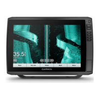
The Garmin ECHOMAP™ ULTRA is a marine chartplotter designed for navigation, sonar, and data sharing on vessels. It offers both bail mounting and flush mounting options, allowing for flexible installation in various boat dashboards. The device is built with a polycarbonate plastic material and has an IEC 60529 IPX7 water rating, meaning it can withstand incidental exposure to water up to 1 meter for 30 minutes. It operates within a temperature range of -15° to 55°C (5° to 131°F).

Technical Specifications:

The ECHOMAP™ ULTRA series includes 10-inch and 12-inch models, each with specific dimensions and weight:

  • 10-Inch Models:

    • Dimensions (W x H x D): 29.5 x 19.5 x 9.8 cm (11.6 x 7.7 x 3.9 in.)
    • Display size (W x H): 21.7 x 13.6 cm (8.5 x 5.4 in.) with a 25.4 cm (10 in.) diagonal
    • Weight: 1.8 kg (4.1 lb.)
    • Max. power draw: 34 W
    • Typical current draw at 12 Vdc (RMS): 2.8 A
    • Max. current draw at 12 Vdc (RMS): 3 A
    • Wireless frequencies and protocols: 2.4 GHz @ 17.2 dBm nominal
  • 12-Inch Models:

    • Dimensions (W x H x D): 34.1 x 22.9 x 9.8 cm (13.4 x 9.0 x 3.9 in.)
    • Display size (W x H): 26.1 x 16.3 cm (10.3 x 6.4 in.) with a 30.7 cm (12.1 in.) diagonal
    • Weight: 2.5 kg (5.5 lb.)
    • Max. power draw: 34 W
    • Typical current draw at 12 Vdc (RMS): 3 A
    • Max. current draw at 12 Vdc (RMS): 3.3 A
    • Wireless frequencies and protocols: 2.4 GHz @ 18.5 dBm nominal

Common specifications for all models include:

  • Compass-safe distance: 65 cm (25.6 in.)
  • Clearance to next obstruction behind chartplotter: 150 mm (6 in.)
  • Input voltage: From 9 to 18 Vdc
  • Fuse: 8 A
  • NMEA 2000 LEN @ 9 Vdc: 1
  • NMEA 2000 draw: 39 mA max.
  • Memory card: 2 microSD™ card slots; 32 GB max. card size
  • The device features one internal NMEA 0183 port for connecting to NMEA 0183 compliant devices. Power and ground wires can be extended using 1.31 mm² (16 AWG) or larger wire, while NMEA 0183 or alarm wires require .33 mm² (22 AWG) wire.

Usage Features:

The ECHOMAP™ ULTRA is designed for comprehensive marine use, offering connectivity for various functions:

  • Power and NMEA 0183 Devices: The device connects to power and can integrate with NMEA 0183 devices for data exchange.
  • Transducer Connectivity: It supports 12-pin transducers and Panoptix™ LiveScope™ LVS12 12-pin transducers for advanced sonar capabilities. Users are advised to consult garmin.com/transducers or a local Garmin dealer to select the appropriate transducer.
  • NMEA 2000® Network Integration: The device can connect to an existing NMEA 2000 network to share data from compatible devices like GPS antennas or VHF radios. It's important to note that the device is not powered through the NMEA 2000 network and requires a separate power source. A NMEA 2000 Power Isolator (010-11580-00) is recommended for installations where the existing NMEA 2000 network manufacturer is unknown.
  • Garmin Marine Network: It facilitates sharing sonar, LiveScope sonar, charts, and user data across the Garmin Marine Network.
  • Ground Screw: A dedicated ground screw is provided for proper grounding.
  • NMEA 2000 PGN Information: The device supports a wide range of NMEA 2000 PGNs for both transmit and receive functions, including:
    • Transmit and Receive: ISO acknowledgment, ISO request, ISO address claim, NMEA: Command, request, and acknowledge group function, Product information, Vessel heading, Speed: Water referenced, Water depth, GNSS DOPs, Radio frequency, mode, and power, Wind data, Temperature.
    • Transmit Only: Transmit and receive PGN list group function, Magnetic Variance, Position: Rapid update, COG and SOG: Rapid update, GNSS position data, Cross track error, Navigation data, Navigation route and waypoint info, GNSS satellites in view.
    • Receive Only: Rudder, Vessel heading, Engine parameters: Rapid update, Engine parameters: Dynamic, Transmission parameters: Dynamic, Engine parameters: Static, Fluid level, AIS class A position report, AIS class B position report, AIS class B extended position report, AIS class A static and voyage related data, AIS SAR aircraft position report, Nautical leeway angle, AIS safety-related broadcast message, DSC call information, Environmental parameters, Environmental parameters (obsolete), Humidity, Actual pressure, Small craft status.

Maintenance Features:

  • Corrosion Prevention: To prevent corrosion of metal contacts, unused connectors should be covered with attached weather caps.
  • Noise Reduction: Ferrite beads should be installed on network and transducer cables near the connectors to comply with regulations and reduce noise.
  • Cable Management: Locking rings are provided for cables to ensure tight connections and simplify cable routing. These split-collar locking rings must be installed on cables that do not come with them pre-installed from the factory.
  • Fuse Protection: The power cable includes an in-line fuse holder, and the appropriate fuse must be in place to prevent fire or overheating. Connecting the power cable without the correct fuse voids the product warranty.
  • Grounding: Proper grounding of the device is essential for safety and optimal performance.
  • Rubber Gasket: For flush mounting, a rubber gasket with adhesive is installed on the back of the device to ensure a secure fit.

Installation and Safety:

  • Safety Precautions: Users are warned to wear safety goggles, ear protection, and a dust mask when drilling, cutting, or sanding. The vessel's power supply must be disconnected before installation. The device should only be installed when the vessel is on land or securely docked in calm water.
  • Mounting: The device can be bail mounted or flush mounted. For bail mounting, the bracket serves as a template for drilling pilot holes. For flush mounting, a template is used to cut a precise hole in the dashboard. Care must be taken when cutting the hole to avoid compromising the device's stability.
  • Cable Connections: All necessary cables connect to the cradle, and locking rings are tightened clockwise to secure them.
  • Device in Cradle: The device can be quickly placed into the cradle by pressing a button on the release lever, lifting the lever, placing the device's base, lifting the lever again, tilting the device, and pushing the lever down until it clicks into place. Removal is the reverse process.
  • Product Support: Garmin Product Support is available for assistance with installation difficulties.

Garmin ECHOMAP ULTRA 126s Specifications

General IconGeneral
BrandGarmin
ModelECHOMAP ULTRA 126s
CategoryFish Finder
LanguageEnglish

Related product manuals