EasyManua.ls Logo

Garmin GA 38 - User Manual

Garmin GA 38
6 pages
Print Icon
To Next Page IconTo Next Page
Loading...
GA
38
INSTALLATION INSTRUCTIONS
Important Safety Information
WARNING
See the Important Safety and Product Information guide in the GPS device product box for product warnings and
other important information.
CAUTION
To avoid possible personal injury, always wear safety goggles, ear protection, and a dust mask when drilling,
cutting, or sanding.
NOTICE
When drilling or cutting, always check what is on the opposite side of the surface to avoid damaging the vessel.
This antenna can be installed to provide a stronger GPS signal to a compatible Garmin
®
chartplotter. This
antenna uses a BNC connector to connect to the port labeled ANTENNA or EXT GPS on a compatible Garmin
chartplotter.
Antenna Mounting Considerations
CAUTION
Do not install or store the antenna near strong magnets, including speakers. A strong magnetic field can
damage the antenna.
You can mount the antenna on a flat surface or attach it to a standard 1in. OD, 14threads per inch,
pipe-threaded pole (not included). You can route the cable outside of the pole or through the pole. For best
performance, consider these guidelines when selecting the antenna mounting location.
To ensure the best reception, the antenna should be mounted in a location that has a clear, unobstructed
view of the sky in all directions .
The antenna should not be mounted where it is shaded by the superstructure of the boat , a radome
antenna, or the mast.
The antenna should not be mounted near the engine or other sources of Electromagnetic Interference (EMI)
.
TA-2013/783
GUID-4523A703-20B6-4900-8AA1-7FD4DDDF628D v7September 2023
Question and Answer IconNeed help?

Do you have a question about the Garmin GA 38 and is the answer not in the manual?

Summary

Important Safety Information

General Safety Warnings and Precautions

Covers warnings, cautions, and notices for safe installation and operation.

Antenna Mounting Considerations

Guidelines for selecting an optimal antenna mounting location.

Testing the Mounting Location

Surface Mounting the Antenna

Mounting the Antenna on a Pole

Mounting with Cable Routed Outside Pole

Instructions for mounting the antenna on a pole with the cable routed externally.

Mounting with Cable Routed Through Pole

Instructions for mounting the antenna on a pole with the cable routed internally.

Mounting the Antenna Under the Deck

Specifications

Limited Warranty

Overview

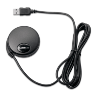
This document provides comprehensive installation instructions for the Garmin GA 38 GPS antenna, designed to enhance GPS signal strength for compatible Garmin chartplotters. The antenna connects via a BNC connector to the ANTENNA or EXT GPS port on the chartplotter.

Function Description

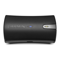
The Garmin GA 38 is an external GPS antenna engineered to provide a robust and reliable GPS signal to compatible Garmin chartplotters. Its primary function is to acquire and relay satellite signals, ensuring accurate positioning and navigation data for marine applications. By offering a dedicated external antenna, the GA 38 mitigates signal degradation that might occur with internal antennas, especially in challenging environments where line-of-sight to GPS satellites is obstructed. This results in improved performance, faster satellite acquisition, and more consistent location tracking. The antenna is built to withstand marine conditions, featuring a durable, gasketed, high-impact plastic alloy casing and an IEC 60529 IPX7 water rating, making it suitable for exposed mounting on vessels.

Usage Features

The GA 38 antenna offers versatile mounting options to accommodate various vessel configurations and optimize signal reception.

Antenna Mounting Considerations:

  • Optimal Reception: For best performance, the antenna should be mounted in a location with a clear, unobstructed view of the sky in all directions. This minimizes signal blockage and ensures consistent satellite acquisition.
  • Obstruction Avoidance: It is crucial to avoid mounting the antenna where it might be shaded by the boat's superstructure, other antennas (like radome antennas), or the mast. These obstructions can significantly degrade GPS signal quality.
  • EMI Avoidance: The antenna should not be mounted near the engine or other sources of Electromagnetic Interference (EMI), as EMI can disrupt signal reception and accuracy.
  • Magnetic Field Avoidance: Users are cautioned against installing or storing the antenna near strong magnets, including speakers, as strong magnetic fields can damage the antenna's internal components.
  • Ferrous Metal Avoidance: The antenna should also not be mounted near known ferrous metal objects such as toolboxes or compasses, which can interfere with its operation.
  • Radar and VHF Antenna Proximity: When a radar is present, the antenna should be mounted above the radar's path. If necessary, it can be mounted below the radar's path, but above is preferred. Additionally, the antenna should not be mounted directly in the path of the radar or within 1 meter (3 ft.) of a VHF radio antenna or the path of a radar, to prevent interference.

Mounting Options:

  1. Surface Mounting:

    • This method involves securing the antenna directly to a flat surface on the vessel.
    • A surface-mount bracket serves as a template for drilling pilot holes and a central cable hole.
    • It is recommended to use a countersink bit for fiberglass surfaces to prevent cracking of the gel-coat layer when screws are tightened.
    • The cable is routed through the center hole and connected to the antenna.
    • A large gasket ensures a watertight seal between the antenna and the mounting surface.
    • The antenna is twisted clockwise onto the bracket to lock it in place and secured with an M3 set screw.
    • The cable should be routed away from sources of electronic interference.
  2. Pole Mounting (Cable Routed Outside the Pole):

    • The antenna can be attached to a standard 1 in. OD, 14 threads per inch, pipe-threaded pole (not included).
    • The cable is routed through a pole-mount adapter and placed in a vertical slot along its base.
    • The adapter is screwed onto the pole, and the cable is connected to the antenna.
    • The antenna is placed on the adapter and twisted clockwise to lock it in place, then secured with an M3 set screw.
    • Optionally, marine sealant can be used to fill any remaining gap in the vertical cable slot for added weather protection.
    • The pole is then attached to the boat, and the cable is routed away from interference sources.
  3. Pole Mounting (Cable Routed Through the Pole):

    • This method also uses a standard 1 in. OD, 14 threads per inch, pipe-threaded pole.
    • A hole is drilled through the pole for the cable to pass through.
    • The pole is fastened to the boat, and the pole-mount adapter is threaded onto the pole.
    • The cable is routed through the pole and connected to the antenna.
    • The antenna is placed on the adapter and twisted clockwise to lock it in place, then secured with an M3 set screw.
  4. Under-Deck Mounting:

    • This option is suitable for mounting the antenna beneath a fiberglass surface only, as metal surfaces will block GPS signals.
    • The under-deck mounting kit (supplied with white antenna models) includes adhesive pads.
    • Adhesive pads are placed on the under-deck mounting bracket, and the antenna is placed into the bracket.
    • The bracket is then adhered to the mounting surface and further secured with screws.
    • Users are advised to verify that the screws are short enough to avoid penetrating through the surface.
    • The cable is connected to the antenna and routed away from electronic interference.

Maintenance Features

The Garmin GA 38 is designed for minimal maintenance, focusing on durable construction and proper installation to ensure long-term performance.

  • Durable Construction: The antenna features a fully gasketed, high-impact plastic alloy case and an IEC 60529 IPX7 water rating, providing robust protection against marine elements such as water ingress, UV exposure, and physical impacts. This inherent durability reduces the need for frequent repairs or replacements.
  • Secure Connections: The use of BNC connectors for cable attachment and M3 set screws for securing the antenna to its mounts ensures stable and reliable connections that are less prone to loosening due to vibration or environmental factors.
  • Optional Sealing: For pole-mounted installations where the cable is routed outside the pole, the option to fill the vertical cable slot with marine sealant provides an additional layer of protection against water intrusion, further enhancing the antenna's longevity in harsh marine environments.
  • Interference Management: The installation guidelines emphasize routing the cable away from sources of electronic interference. This proactive measure helps maintain signal integrity and prevents performance degradation, reducing the need for troubleshooting related to poor signal quality.
  • Pre-Installation Testing: The manual strongly recommends temporarily securing the antenna in the preferred mounting location and testing it for correct operation before permanent installation. This allows users to identify and resolve potential interference issues or suboptimal signal strength by relocating the antenna, thereby preventing future performance problems and associated maintenance efforts.
  • Safety Precautions: The document includes important safety information, such as wearing safety goggles, ear protection, and a dust mask when drilling, cutting, or sanding, and checking for obstructions on the opposite side of the surface before drilling. Adhering to these precautions during installation helps prevent damage to the vessel or injury to the installer, indirectly contributing to the long-term integrity of the installation and reducing the likelihood of future maintenance needs arising from improper procedures.

Garmin GA 38 Specifications

General IconGeneral
Product colorWhite

Related product manuals