Do you have a question about the Garmin GMA 345 and is the answer not in the manual?
Details document revisions, dates, and descriptions of changes.
Explains the meaning of a WARNING statement in the manual.
Explains the meaning of a CAUTION statement in the manual.
Explains the meaning of a NOTE statement in the manual.
Manual purpose, intended audience, and installation recommendations.
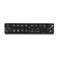
Overview of GMA 342/345 features, capabilities, and differences.
Detailed comparison of features for GMA 342, GMA 345, and GMA 345 3-COM.
Dimensions and weight of the GMA 342/345 unit.
Performance and electrical characteristics like compliance, delay, altitude, and functions.
Input voltage range, leakage current, and unit operation at low voltage.
TSO/ETSO compliance for GMA 342/345 and GMA 345 models.
Deviations received by Garmin from TSO standards for the units.
FCC ID, rules compliance, and RF radiation exposure statement.
Innovation, Science and Economic Development Canada RSS standards compliance.
Overview of installation and checkout, factors affecting installation.
Lists required installation materials and unit configurations.
Lists and describes available accessories for installation.
Details contents of the GMA 342 and GMA 345 standard installation kits.
Lists additional tools, hardware, and supplies needed for installation.
How AUX inputs are selected on GMA 345 3-COM vs. 2-COM units.
Guidance on mounting and cabling the marker beacon antenna.
Guidance for terminating coaxial cable into the D-Sub connector.
FAA approval considerations for pressurized cabin aircraft installations.
Guidelines for wire gauge, routing, and power connections.
Requirements for bonding equipment to aircraft structure for electrical continuity.
Explanation of MASQ function to filter low-level noise.
How to adjust marker beacon sensitivity for earlier indication.
Option to reduce intercom background noise in noisy cockpits.
Allows pilot/copilot to hear music during isolation mode.
Explains DIP switch locations and functions for configuration.
Instructions for entering and using configuration mode via the front panel.
Configuration options available by wiring inputs to ground.
How to retrieve the current software version.
Steps to create an SD card for software updates.
Procedure for loading software onto the unit using an SD card.
Guidance on preventing interference from coupled sources and ground loops.
Requirements for mounting surface and using the GMA unit rack.
Instructions for unpacking and inspecting the unit for damage.
Overview of electrical connections via 44-pin D-sub connectors.
General guidance for installing the antenna.
Instructions for installing shield block backshells.
Information on assembling backshell connectors and grounding system.
Steps for final installation into the unit rack.
Steps for final installation into the unit rack.
Procedures to verify the unit's functionality after installation.
Procedure to check the failsafe operation of the unit.
Steps to verify transceiver, microphone, and audio functionality.
Verifying audio from avionics units and alert sources.
Steps to verify music system functionality with MUSIC 1 and MUSIC 2 inputs.
Procedure for pairing and testing Bluetooth music playback.
How to test speaker output and Passenger Address (PA) mode.
Procedure to test marker beacon tones and lamp annunciation.
Verifying operation of other installed inputs and outputs.
How to access and interpret diagnostic information on the unit.
Description of the rear unit connectors J3401 and J3402.
Overview of pin numbering for rear connectors.
Pin assignments for the J3401 connector.
Detailed list of pin names and I/O for J3401.
Continuation of pin assignments for J3401.
Pin assignments for the J3402 connector.
Detailed list of pin names and I/O for J3402.
Details on power and ground pins for aircraft power input.
Details on connecting aircraft power and ground pins.
How lighting bus inputs control backlighting brightness.
Specifications for RS-232 output and voltage swing.
Overview of audio and microphone connections.
Pin assignments for microphone audio inputs and key signals.
Continues pin assignments for microphone inputs and keys.
Pin assignments for COM audio and mic key signals for 2-COM and 3-COM units.
Pin assignments for alert audio inputs.
Continues pin assignments for alert audio inputs.
Pin assignments for receiver, auxiliary, and navigation audio inputs.
Pin assignments for failsafe warning audio input.
Pin assignments for music input signals.
Pin assignments for wired telephone audio and microphone.
Information on headset output capabilities and mono/stereo jack behavior.
Detailed pin assignments for pilot, copilot, and passenger headset outputs.
Pin assignments for speaker audio output.
Overview of discrete input functions like ICS KEYs, COM Swap, Play key.
Pin assignments for discrete output signals.
Details on marker lamp outputs and their control.
Details on marker lamp outputs and their control.
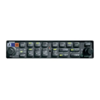
Mechanical compatibility and reuse of parts when upgrading from GMA 340.
Notes on pin modifications and COM3 interface for GMA 340 upgrades.
Pin-to-pin connection mapping for GMA 340 to GMA 342/345 upgrades.
Shows the physical dimensions and outline of the GMA 342/345 unit.
Illustrates the GMA 342/345 unit rack and connector kit assembly.
Provides panel cutout dimensions for different installation options.
Important notes and symbols used in interconnect diagrams.
Example interconnect diagram for the J3401 connector.
Example interconnect diagram for the J3402 connector.
Example diagram showing lighting bus connections.
Example diagram for mono audio connections.
Example diagram for wiring four passenger headsets.
Example diagram showing LEMO connector wiring.
Connector layout for non-3-COM units.
Connector layout for 3-COM units.
| Display Type | LCD |
|---|---|
| Audio Channels | 6 |
| Bluetooth | Yes |
| 3D Audio | Yes |
| Marker Beacon Receiver | Yes |
| Voltage | 14/28 VDC |
| Intercom Positions | 6 |
| Weight | 1.6 lbs |
| Interfaces | RS-232 |
| Audio Outputs | 2 stereo, 4 mono |
| Audio Input | Music |