EasyManua.ls Logo

Garmin GMA 35 User Manual

Garmin GMA 35
55 pages
To Next Page IconTo Next Page
Page #1 background imageLoading...
Page #1 background image
The following les have been archived under the above ARCHIVE FILENAME.
Filename File Contents
Date:
Drafter:
TITLE:
PART NO:
SIZE
A
Scale:
N/A
REV.
Sheet of
REVISIONS
SPECIFICATION
CONTROL
DRAWING
REV. DATE DESCRIPTION ECO NO.
Garmin Ltd. or its subsidiaries
c/o Garmin International, Inc.
1200 E. 151st Street
Olathe, Kansas 66062 U.S.A.
CONFIDENTIAL
This drawing and the specications contained herein are the property of Garmin
Ltd. or its subsidiaries and may not be reproduced or used in whole or in part as
the basis for manufacture or sale of products
without written permission .
190-00858-11.pdf
190-00858-11
GMA 35 Installation Manual
H
1 1
JGS
1/20/11
F 9/2/15 Added the GMA 35c 132290
G 10/2/15 Included FCC commetnts 133098
H 3/22/16 Added European Union and Brazil statements 139773
NOTES:
1. DESCRIPTION: Installation Documentation
2. DISTRIBUTION: This document is intended for electronic distribution.
Portable Document Format, contains Installation Manual and Release Specication
release.indd Adobe InDesign Format, Release Specication
Manual Elements FrameMaker, Formatted Files and Figures
*.* Various supporting illustrations, drawings, and artwork.
Question and Answer IconNeed help?

Do you have a question about the Garmin GMA 35 and is the answer not in the manual?

Garmin GMA 35 Specifications

General IconGeneral
BrandGarmin
ModelGMA 35
CategoryGPS
LanguageEnglish

Summary

INFORMATION SUBJECT TO EXPORT CONTROL LAWS

Declaration of Conformity

Garmin's declaration of product compliance with EU directives.

Anatel Warning

Warning regarding radio interference for Brazilian operations.

DEFINITIONS OF WARNINGS, CAUTIONS, AND NOTES

GMA 35 HARDWARE MOD LEVEL HISTORY

1 GENERAL DESCRIPTION

1.1 Introduction

Provides overview of manual purpose and audience.

1.2 Equipment Description

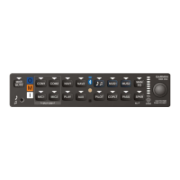
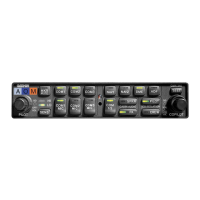
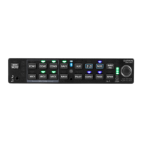
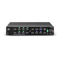
Details the GMA 35/35c audio panel functions and features.

1.2.1 Interface Summary

Lists key interface features and capabilities of the GMA 35.

1.3 Technical Specifications

Outlines performance and physical specifications for the GMA 35.

1.3.1 Physical Characteristics

Details dimensions and weights for the GMA 35 unit.

1.3.2 Electrical Characteristics

Covers environmental compliance, temperature, altitude, and audio specs.

1.3.3 Power Requirements

Specifies input voltage and power consumption for the GMA 35.

1.4 Certification

Discusses TSO/ETSO approval standards and requirements.

1.4.1 TSO/ETSO Compliance

Lists TSO/ETSO compliance for various functions of the GMA 35.

1.4.2 TSO/ETSO Deviations

Details any granted deviations from TSO/ETSO standards.

1.4.3 Non-TSO Functions

Describes functions tested but not covered by TSO/ETSO.

1.4.4 Transmitter Grant of Equipment Authorization

Covers FCC and Industry Canada compliance for radio transmission.

1.5 Reference Documents

Lists additional manuals for GMA 35 installation.

1.6 Operating Instructions

Provides basic operating guidance for the GMA 35.

1.6.1 Intercom

Explains how to enable various intercom modes.

1.6.2 Adjusting Intercom Volume

Details steps to adjust intercom volume settings.

1.6.3 Adjusting Intercom Squelch

Describes how to adjust intercom squelch settings.

1.6.4 Passenger Address System

Instructions for using the Passenger Address system.

1.6.5 Digital Clearance Player

How to use the digital clearance player functions.

1.6.6 Selecting/deselecting MUSIC1/MUSIC2 input

Guide to managing MUSIC1/MUSIC2 inputs.

RF Exposure Compliance Statement

2 INSTALLATION OVERVIEW

2.1 Introduction

Overview of installation information and guidance.

2.2 Installation Materials

Lists available GMA 35 part numbers and accessories.

2.2.1 Equipment Available

Details optional accessories for the GMA 35.

2.2.2 Additional Equipment Required

Lists cables and jacks needed for installation.

2.3 Installation Considerations

Discusses general installation practices and requirements.

2.3.1 Marker Beacon Antenna Installation

Specific guidance for installing the marker beacon antenna.

2.3.1.1 Location Considerations

Recommendations for optimal marker beacon antenna placement.

2.3.1.2 Marker Beacon Antenna Mounting

Instructions for mounting the marker beacon antenna.

2.3.1.3 Marker Beacon Antenna Cable

Guidance on routing and precautions for antenna cables.

2.3.1.4 Marker Beacon Antenna Cable Installation

Details on terminating the marker beacon coaxial cable.

2.3.1.5 Bluetooth Antenna/Cable Kit Installation (GMA 35c only)

Instructions for installing the Bluetooth antenna kit.

2.4 Cabling & Wiring

General guidance on wiring and cable routing.

2.5 Cooling Air

Considerations for managing thermal conditions during installation.

2.6 Mounting Requirements

Specifies requirements for mounting the GMA 35 unit rack.

2.7 Installation Approval Considerations for Pressurized Aircraft

Requirements for installations on pressurized aircraft.

2.8 Electrical Noise

Advice on minimizing electrical noise and ground loops.

3 INSTALLATION PROCEDURE

3.1 Unpacking Unit

Steps for unpacking and inspecting the unit.

3.2 Antenna Installation

General instructions for antenna installation.

3.3 Antenna Cable Connectors

Guidance on BNC connector assembly for antenna cables.

3.4 Electrical Connections

Details on making electrical connections using D-sub connectors.

3.5 Backshell Assembly

Instructions for assembling the GMA 35 backshell connectors.

3.6 GMA 35 Unit Installation

Steps for installing the GMA 35 unit into its rack.

3.7 Post Installation Configuration & Checkout

Procedures for configuring and testing the installed GMA 35.

3.7.1 Verify Failsafe Operation with a Mono Headset

Steps to verify failsafe operation with a mono headset.

3.7.2 Verify Installed Transceivers (COMs) are able to Transmit and Receive

Procedure to check COM transceiver transmit/receive functionality.

3.7.3 Verify Audio from Installed Receiver and Alert Sources

Steps to verify audio from receivers and alert sources.

3.7.4 Verify Speaker Output (if installed)

Procedure to test speaker output.

3.7.5 Verify ICS (Intercom System) Operation

Checks for proper intercom system functionality.

3.7.6 Verify Telephone and Music Operation (if installed)

Verifies telephone and music input functionality.

3.7.7 Marker Beacon Operation (if installed)

Procedure to test marker beacon tones and lamps.

3.7.8 Other Optionally Installed or Configured Inputs/Outputs

Verifies operation of other configurable I/O.

3.8 Continued Airworthiness

Information on ongoing maintenance and airworthiness.

4 SYSTEM INTERCONNECTS

4.1 Pin List

Detailed list of pin assignments for connectors.

4.1.1 J3501 Connector

Pinout details for the J3501 connector.

4.1.2 J3502 Connector

Pinout details for the J3502 connector.

4.2 Power

Information on aircraft power connections.

4.2.1 Aircraft Power

Specifics on aircraft power input pins.

4.3 Serial Data

Details on serial data (RS-232) connections.

4.3.1 RS-232

Pin assignments for RS-232 communication.

4.4 Lighting

Information on lighting bus inputs.

4.5 Audio Inputs and Outputs

Comprehensive list of audio I/O connections.

4.5.1 COM Audio Inputs and Outputs

Pin assignments for COM audio interfaces.

4.5.2 NAV Audio Inputs

Pin assignments for NAV audio inputs.

4.5.3 Receiver Audio Inputs

Pin assignments for receiver audio inputs.

4.5.4 Telephone

Pin assignments for telephone audio and microphone.

4.5.5 Pilot/Copilot

Pin assignments for pilot and copilot audio/mic connections.

4.5.6 Passenger

Pin assignments for passenger audio and microphone inputs.

4.5.7 Alert Inputs

Pin assignments for various alert audio inputs.

4.5.8 Speaker Outputs

Pin assignments for speaker audio outputs.

4.6 Music Inputs

Pin assignments for music audio inputs.

4.7 Mic Keys

Pin assignments for microphone key inputs.

4.8 Marker Beacon

Pin assignments for marker beacon functionality.

4.9 Miscellaneous Configurable I/O

Pin assignments for configurable I/O functions.

Appendix A INSTALLATION CONSIDERATIONS FOR UPGRADING FROM A GARMIN GMA 340

A.1 Mechanical Considerations

Mechanical aspects for upgrading from GMA 340.

A.2 Electrical Considerations

Electrical aspects for upgrading from GMA 340.

Appendix B OUTLINE AND INSTALLATION DRAWINGS

Appendix C INTERCONNECT DRAWINGS

Part Information

Item Attribution

Details on document review and item attribution.

Related product manuals