Do you have a question about the Garmin GTS 8 Series and is the answer not in the manual?
Presents mechanical and electrical installation requirements for the GTS 8XX/GPA 65.
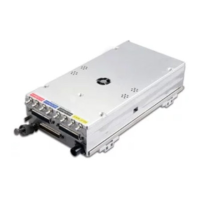
Details the GTS 8XX as a microprocessor-based LRU for traffic advisories.
Summarizes differences between various GTS 8XX models documented in this manual.
Outlines the communication interfaces used by the GTS 8XX system.
Details the availability of the Environmental Qualification Form for the GTS 8XX/GPA.
Lists the physical dimensions and weights of the GTS 8XX and GPA 65 units.
Contains general specifications such as temperature range, humidity, and altitude.
Details the power consumption and current draw for the GTS 8XX units.
Lists the applicable TSO/ETSOs for the GTS 8XX/GPA 65 systems.
Details the deviations granted for the TSO/ETSO standards for the GTS 8XX.
Lists TSO/ETSO deviations specific to the GTS 800 model.
Lists TSO/ETSO deviations specific to the GTS 820 model.
Lists TSO/ETSO deviations specific to the GTS 850 model.
Provides hardware equipment information for installing the GTS 8XX/GPA 65.
Lists the available part numbers for the GTS 8XX and GPA 65 units.
Lists accessories required for installation of the GTS 8XX and GPA 65.
General considerations for fabricating wiring harnesses and installing equipment.
Specifics for antenna installations on pressurized cabin aircraft and composite aircraft.
Guidelines for positioning the GTS 8XX top and optional bottom antennas.
Requirements for electrically bonding equipment to the aircraft structure.
Details wire gauge, routing, and circuit breaker requirements.
Details coaxial cable assembly and termination requirements.
Specifics for connecting coaxial cables for GTS 800 installations.
Specifics for connecting coaxial cables for GTS 820/850 installations.
Instructions for fabricating coaxial cable assemblies using QMA connectors.
Step-by-step assembly instructions for coaxial cable assemblies.
Procedures for repairing or reworking coaxial cable assemblies.
Information regarding cooling requirements for the GTS 8XX and GPA 65.
Details on mounting the GTS 8XX unit using installation racks.
Steps for unpacking and visually inspecting the equipment for damage.
Guidelines for the installation of wiring harnesses and connectors.
Instructions on how to engage and disengage QMA connectors.
Description of connector kits, backshells, and configuration modules.
Refers to outline and installation drawings in Appendix A for unit mounting.
Actions to perform after equipment installation for calibration and verification.
Details how to perform configuration and software uploads for the GTS 8XX.
Describes the Normal mode tab of the GTS 8XX Install Tool for system status.
Describes the Configuration mode tab for changing installation settings.
Describes the Upload tab for viewing and updating system software versions.
Notes that the Debug tab is reserved and not available for field installation.
Refers to other manuals for configuration of CDTI displays.
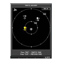
Describes the self-test feature for calibration and display verification.
Procedure for using a ramp tester to verify operational and surveillance functions.
Procedure to verify auto-calibration and antenna connections.
Steps for installing the GA 58 antenna, including mounting and sealing.
Steps for installing the GPA 65 PA/LNA unit.
Notes regarding the maintenance of the GTS 8XX and GPA 65 as 'on condition'.
Provides a list of pin functions for the GTS 8XX unit.
Details the pinout for the P8001 digital connector.
Details the pinout for the P8002 analog and discrete connector.
Details the pinout for the P8003 power supply connector.
Provides a list of pin functions for the GPA 65 unit.
Details the pinout for the P651 connector on the GPA 65.
Covers the power input requirements for aircraft power.
Details the aircraft power connections and redundancy.
Describes remote control of unit power ON/OFF states.
Details the power supply connections for the GPA 65 PA/LNA module.
Details the RS-232 communication interface and its specifications.
Details the RS-422 communication interface and its specifications.
Details the ARINC 429 communication interface and its electrical specifications.
Details the Ethernet communication interface and IEEE standard compliance.
Details the USB interface for unit configuration and software uploads.
Describes the connections and function of the configuration module.
Provides heading information from gyros via AC reference signals.
Details the AC inputs for heading signals, including frequency and voltage.
Details the analog inputs for radar altimeter data.
Details heading inputs from directional gyros via synchro signals.
Details the outputs for alert audio signals.
Describes active low discrete input signals for system control.
Describes active high discrete input signals for system control.
Details annunciator output signals for system status.
Details the Mutual Suppression Bus compliant with ARINC 735A.
Shows dimensions and mounting details for vertical installation of GTS 8XX.
Illustrates components and layout for vertical installation of GTS 8XX.
Shows dimensions and mounting details for horizontal installation of GTS 8XX.
Illustrates components and layout for horizontal installation of GTS 8XX.
Shows dimensions and mounting details for the GPA 65 unit.
Illustrates components and layout for GPA 65 installation.
Shows dimensions and mounting details for the GA 58 antenna.
Provides general notes and symbol designations for interconnect diagrams.
Wiring diagram example for GTS 820/850 and GPA 65 interconnects.
Wiring diagram example for GTS 800 interconnects.
Wiring diagram example for GTS 8XX within a G1000 system.
Wiring diagram example for GTS 8XX with GNS 4XX/5XX and GMX 200.
Wiring diagram example for GTS 8XX with GMA, HSI, and Altimeter.
Diagram for connecting the GTS 8XX via USB dongle cable.
Diagram illustrating discrete signal connections for the GTS 8XX.
Wiring diagram example for the GTS 8XX configuration module.