7. Reconnect the Power Supply Module and Battery Pack Module as shown;
8. Reassemble the system and test.
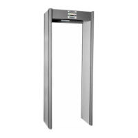
11.7 STABILIZER BASE INSTALLATION
TOOLS REQUIRED PARTS LIST
•1/4” Electric Drill Motor •2-Mounting Plate
•1/4” (6mm) Nut Driver or Hex Socket •4-Screw #8x2” Self-Tapping 1/4”
•Tape Measure •1-Drill Bit 3/32”
•Liquid Soap •1-Instruction Sheet
•#2 Phillips Screwdriver
Procedure (NOTE: Install mounting plates before
assembling the archway)
11.7.1 Examine the location and determine the best routing for the power cord.
11.7.2 For each panel, remove and discard the two (2) rubber bumpers located on the bottom of the pan-
els. these holes will be used for attaching mounting plates to panels. These holes will be sued for
attaching mounting plates to panel.s. Discard rubber bumpers and screws.
11.7.3 Using the supplied 3/32” (2.3mm) drill bit, extend the depth of the mounting holes to 2” (50mm) deep.
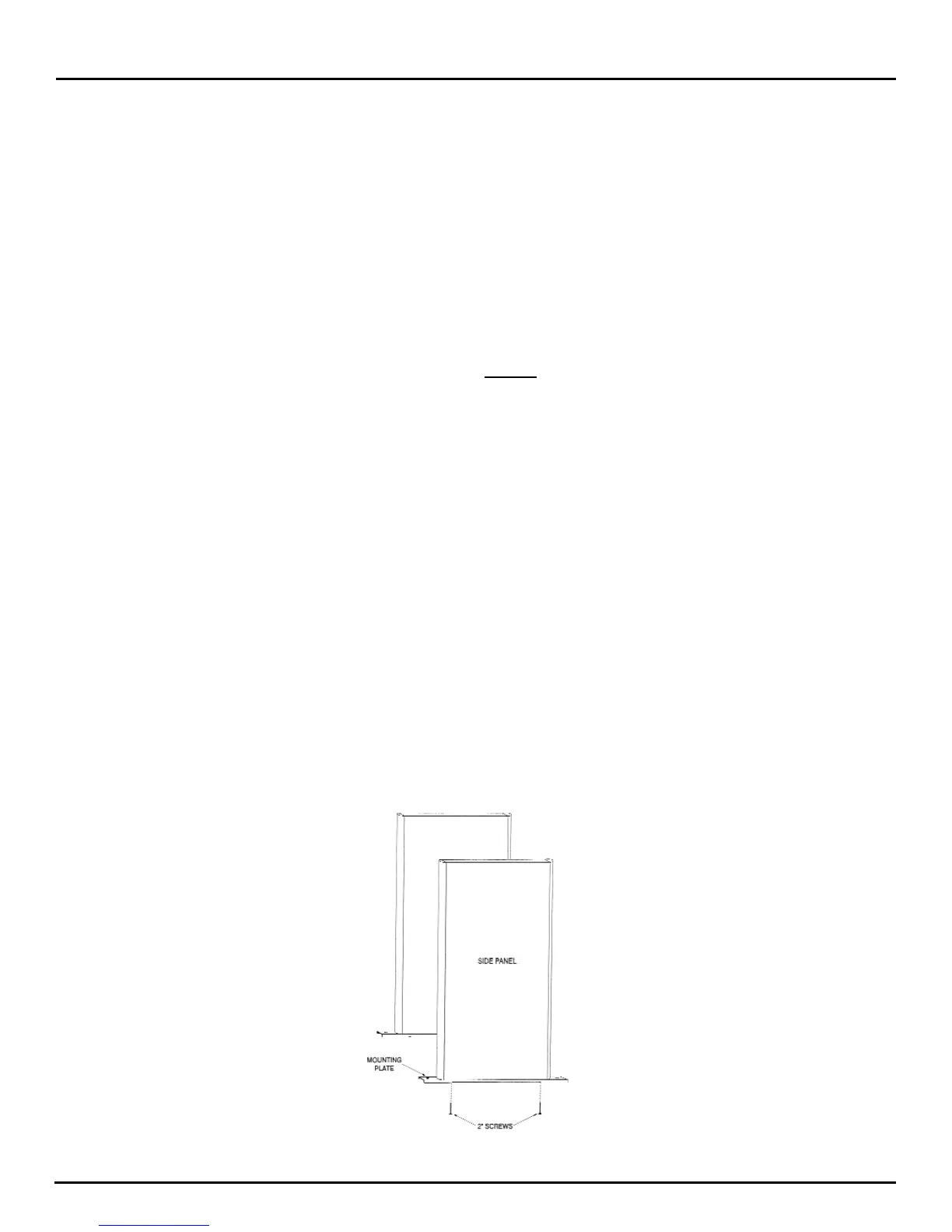
11.7.4 Attach the plates (with the edges pointing away from the panel) using the supplied 2” long screws.
NOTE:
A small amount of liquid soap will make the installation easier.
CAUTION:
The power cord must be installed in the correct Panel location (see section 3.2) before the plate
can be secured. DO NOT PINCH the cord between the panel and the plate. Ensure that the head of
the screw is tight against the plate to prevent the panels from sliding.
11.7.5 Assemble the unit.
MT 5500
User Manual
© 2006 GARRETT METAL DETECTORS 44 PN 1530200.F.0506