Magnum 4K8 Switches Installation and User Guide (10/04)
19
www GarrettCom com
..
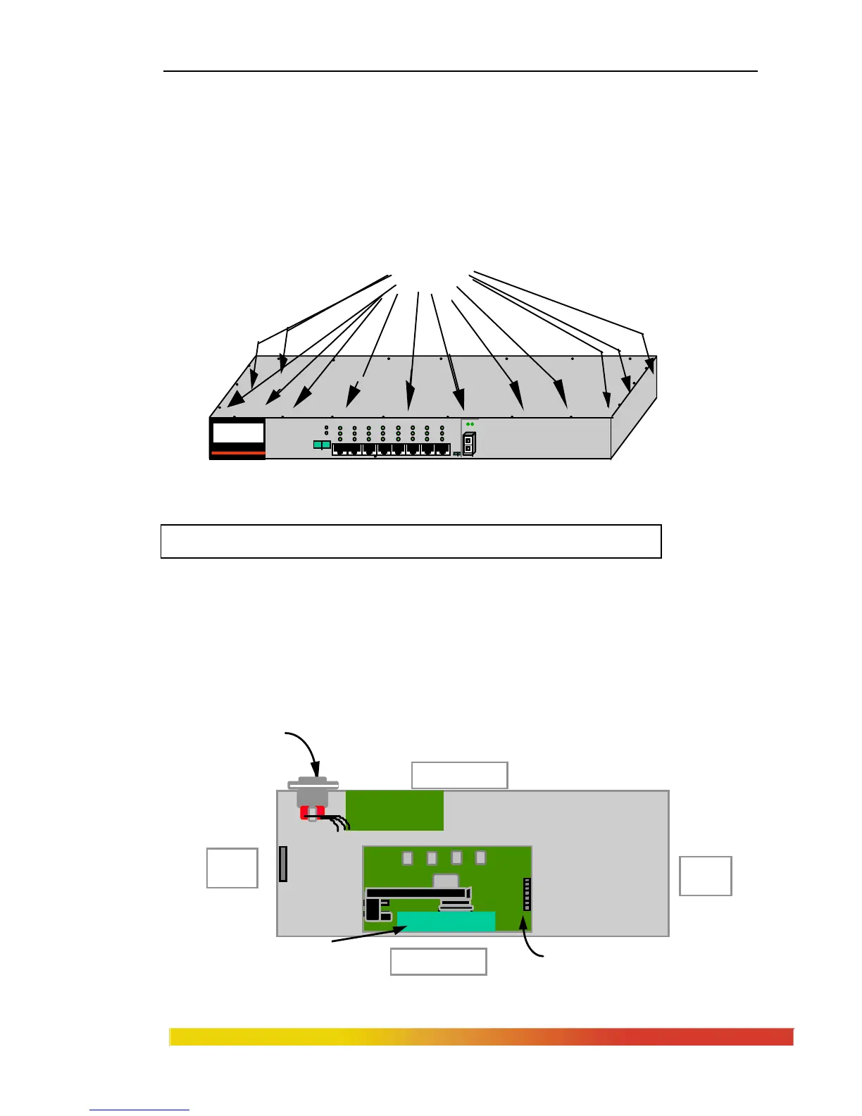
Step 2. Remove Chassis Cover
The Magnum 4K8 chassis are combined with top and bottom part and
assembled together with the help of 20 Philips head screws. There are 7 screws located
on front-top of the unit and three screws each on the left and right edges. Remove these
screws. Once these are removed, the top cover is easily lifted off the chassis base. When
the chassis top cover has been removed, the interior of the unit is exposed.
Figure 3.4.1a: Removing Chassis Cover
Caution: Be careful not to disturb the power supply.
Attention: Faites attention à ne pas déranger l'alimentation d'énergie
Looking down into the Magnum 4K8 unit, notice that there are one FPM
connector sockets located on the extreme right in front for FPM card position.
The Easier way to find the FPM socket, is to look exactly behind the Fiber
port module slot.(See Figure 3.4.1b)
Figure 3.4.1b: Magnum 4K8 Switch, Top View without Chassis Cover
MAGNUM 4K-Series
Ethernet 10/100 Switch
1 2 3 4 5 6 7 8
POWER
ERROR
L/A
SPEED
F/H
UPLINK
= X
F
H
A L
F
H
20 Phillips Head Screws on Top
PWR
TopChassis Cover
Front of Unit
Media Connector
with electronic
elements
Right
Side
Left
Side
Power Supply Board
LED Status Slot
FPM Slots
AC Power Input
Back of Unit