MGC Pump User’s Manual
UM-MGC-P v1.06 14 of 19
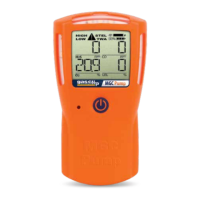
The detector will rst automatically zero the sensors at the current baseline reading, then the detector will prompt
to "APPLY GAS." Once the screen displays “APPLY GAS”, apply gas to the detector’s gas inlet. As the detector detects
gas, the sensor readings will be displayed and adjusted throughout the calibration.
Once calibration is complete, the detector will display the next calibration date before returning to normal
(alarming) operation. If a sensor fails to calibrate, the detector will display an error for the failed sensor. Check your
gas connections and concentration before attempting a second calibration. If a sensor fails to calibrate after a
second attempt, contact GCT for either warranty replacement or
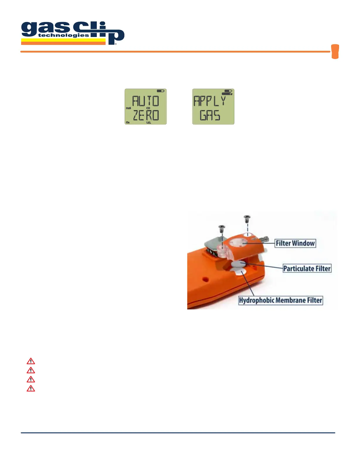
Filter Replacement
The detector includes both a hydrophobic membrane lter and a particulate lter to keep the internal pump and
sensor areas free of water and debris. If these lters become blocked, then the detector will be unable to continue
sampling and the pump will enter into a pump blocked
alarm. Looking at the lter window will typically indicate
a clean (white) or dirty (dark color) condition.
If the lters require replacement, then remove the gas
inlet by loosening the two screws.
Replace the hydrophobic and/or particulate lters as
required, then reassemble to continue operating the
detector. replacement sensor(s).
Pump Testing
Anytime that the gas tubing has been changed or reconnected to the detector, the sampling system should be
tested by blocking the end of the tube. When the gas ow is blocked, the detector will go into alarm and disable the
pump. Press the button to reactivate the pump.
Warning: Perform a blocked ow test before each day’s use.
Warning: Perform a blocked ow test any time the sampling system is changed.
Warning: Do not use silicon tubing with the catalytic bead LEL sensor.
Warning: Failure to detect a block may indicate a leak in the sampling system.
 Loading...