MGC Pump User’s Manual
UM-MGC-P v1.06 4 of 19
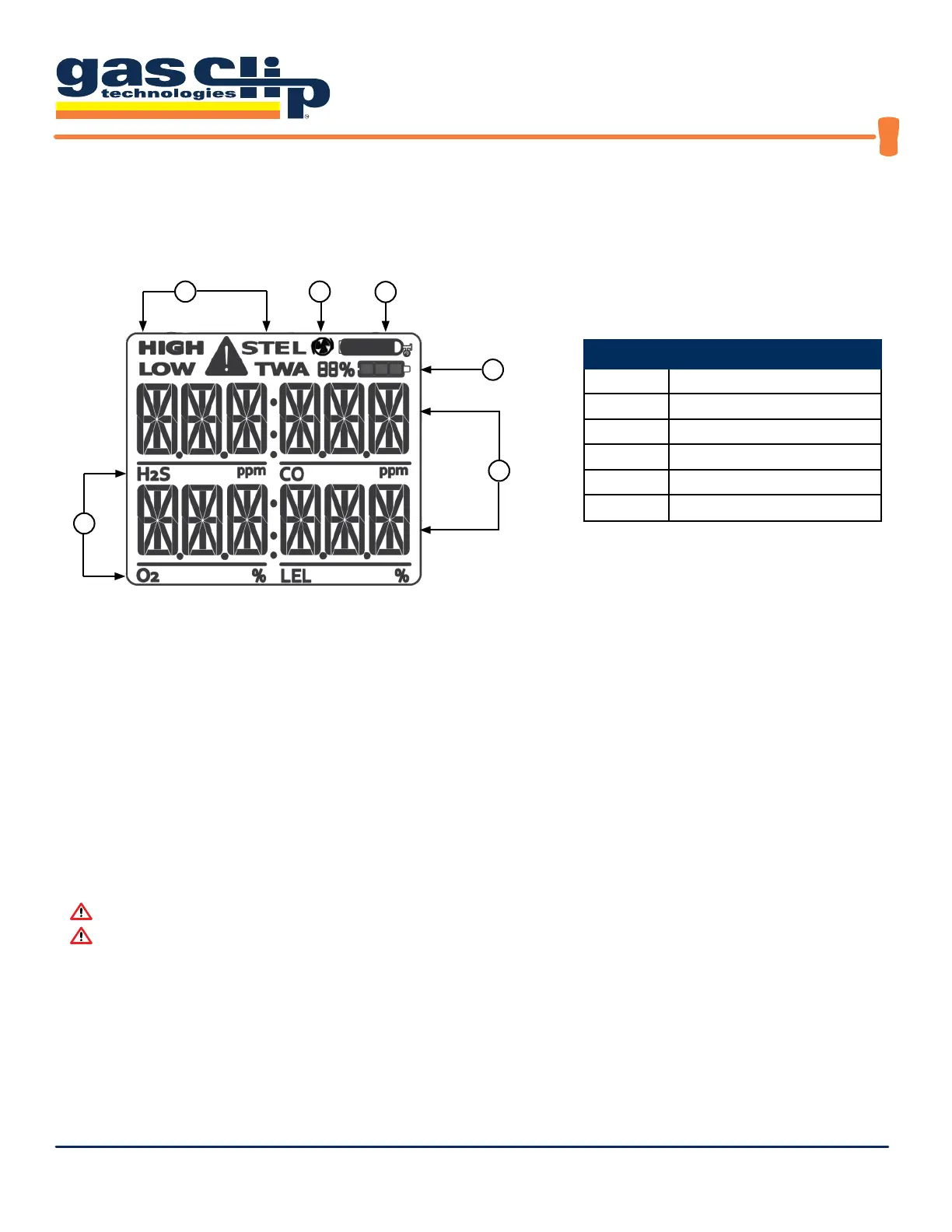
Display Layout
Display Details
• When a gas is reading at, or above, its alarm thresholds, the gas identier icon will ash and the associated
alarm condition icon will display.
• The pump status icon will be turned on whenever the pump is operating.
• During a pump alarm (pump blocked), the pump status icon will ash with the warning icon.
• During calibration or a bump test, the calibration bottle will be displayed when it is time to apply gas.
• The battery is displayed in 3 bars, as well as a percentage. The percentage calculation is approximate and can be
used to provide a rough estimation of the time remaining.
Warning: Users must familiarize themselves with the icons in both non-alarm and alarm states.
Warning: If the display is missing icons or cannot be clearly read, discontinue use and contact GCT.
DISPLAY COMPONENTS
Entry Description
1 Alarm Condition
2 Pump Status
3 Calibration/Test Mode
4 Battery Charge Level
5 Gas Readings
6
Gas Identiers
2
3
4
5
6
1
 Loading...