EasyManua.ls Logo

GASSONIC Observer-i User Manual

GASSONIC Observer-i
89 pages
To Next Page IconTo Next Page
Page #1 background imageLoading...
Page #1 background image
GAS
S
Ultra
s
S
ONI
C
s
onic G
a
C
OBS
E
a
s Leak
The
i
docu
m
purp
o
writin
g
Instr
u
Gass
o
speci
f
Part
N
Revi
s
E
RVE
R
Detect
o
i
nformation
a
m
ent may b
e
o
ses and to
g by Gasson
i
u
ction Manu
onic reserv
e
fications and
N
o.
s
ion
-
i
o
r
a
nd technica
l
e
used and d
i
the extent s
p
i
c.
al
e
s the right
designs with
MAN
O
M
l
data disclo
s
i
sseminated
o
p
ecifically a
u
03
-
to change
out prior noti
c
O
bserver
-
M
ANObserv
e
B/03
-
sed in this
o
nly for the
u
thorized in
-
14
published
c
e.
-
i
e
r-i
-
14

Table of Contents

Other manuals for GASSONIC Observer-i

Question and Answer IconNeed help?

Do you have a question about the GASSONIC Observer-i and is the answer not in the manual?

GASSONIC Observer-i Specifications

General IconGeneral
BrandGASSONIC
ModelObserver-i
CategorySecurity Sensors
LanguageEnglish

Summary

2.0 GENERAL DESCRIPTION AND FEATURES

2.1. Artificial Neural Network (ANN)

Essential for distinguishing gas leaks from background noise.

2.3. Detector Outputs

Lists the available output capabilities of the UGLD.

3.0 INSTALLATION

3.1. Mechanical Construction

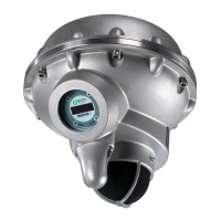
Describes the internal and external construction of the detector.

3.2. Mechanical Operation and Safety

Details safe operating procedures and conditions.

3.3. Mounting

Provides instructions and diagrams for mounting the detector.

3.4. Wiring Diagram

Illustrates the electrical connections for the unit.

3.5. Protective Earth Grounding

Explains the requirements for proper grounding.

4.0 OPERATION AND SETUP

4.2. Normal Operation

Describes the standard operating modes and indicators.

4.3. Setup

Outlines methods for configuring the unit's settings.

4.4. Switching Modes

4.5. User Display & Magnet Interface

4.5.1. Setting / Checking Detection Mode and Analog Output Mode

Configures detection mode and analog output type.

4.5.2. Forced Acoustic Test

Guides on performing a manual acoustic test of the unit.

4.5.3. Setting / Checking Trigger Level (ANN Sensitivity Level)

How to configure alarm trigger levels or ANN sensitivity.

4.5.5. Setting / Checking Delay Time

Adjusts the delay time for alarm activation.

4.5.8. Setting / Checking Factory Default ON / OFF

Resets unit settings to factory defaults.

4.5.10. HART ON/OFF

Enables or disables HART communication.

4.5.12. Modbus Setting: Baud (Channel One)

Configures the baud rate for Modbus channel one.

4.5.13. Modbus Setting: Format (Channel One)

Sets the data format for Modbus channel one.

4.5.14. Modbus Setting: Address (Channel One)

Configures the Modbus address for channel one.

4.5.15. Baud (Channel Two)

Configures the baud rate for Modbus channel two.

4.5.16. Format (Channel Two)

Sets the data format for Modbus channel two.

4.5.17. Address (Channel Two)

Configures the Modbus address for channel two.

5.0 Function Test, Gain Test and Calibration

5.3. Gain Test

Procedure for verifying detector accuracy using the 1701 unit.

5.4. Calibration

Steps for calibrating the Gassonic Observer-i.

6.0 Modbus Digital Interface

6.1. Baud Rate

Selectable baud rates for Modbus communication.

6.2. Data Format

Selectable data formats for Modbus communication.

6.3.2. Modbus Read Response Message

6.4. Modbus Write Command Protocol (Query/Response)

6.4.2. Modbus Write Response Message

6.5. Exception Responses and Exception Codes

6.5.2. Exception Code Field

Lists and explains Modbus exception codes.

6.6. Command Register Locations

6.7. Gassonic Observer-i Command Register Details

6.7.3. Primary Fault Status/Error 1 (02H)

Primary register for fault status and error codes.

6.7.12. Trigger Level (0DH)

Register to set/read the alarm trigger level.

6.7.13. Trigger Delay (0EH)

Register to set/read the alarm delay time.

6.7.14. Comm 1 Address (0FH)

Register to set/read Modbus channel 1 address.

6.7.15. Comm 1 Baud Rate (10H)

Register to set/read Modbus channel 1 baud rate.

6.7.16. Comm 1 Data Format (11H)

Register to set/read Modbus channel 1 data format.

6.7.17. Comm 2 Address (12H)

Register to set/read Modbus channel 2 address.

6.7.18. Comm 2 Baud Rate (13H)

Register to set/read Modbus channel 2 baud rate.

6.7.19. Comm 2 Data Format (14H)

Register to set/read Modbus channel 2 data format.

6.8. Event Logging (30H – 5FH)

6.8.20. Detection Mode (D9H)

Sets the detection mode to Classic or Enhanced.

6.8.21. Enhanced Analog Output Mode (DAH)

Sets the analog output mode for Enhanced.

8.2. Specifications

8.4. Sound Source Calibration