4
Operating Instructions
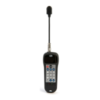
Attaching Sensor
Each of the male and female connectors has a notch on the surface.
Fit the connectors together at the notch and push them together. To
disconnect, hold the collar on the sensor and pull out.
Turn on the power
Press the “Power” key and the LCD screen display appears as follows:
The LCD screen is backlit for use in low light conditions. The screen
and backlight remain on for up to five minutes of inactivity, then the unit
automatically turns off.
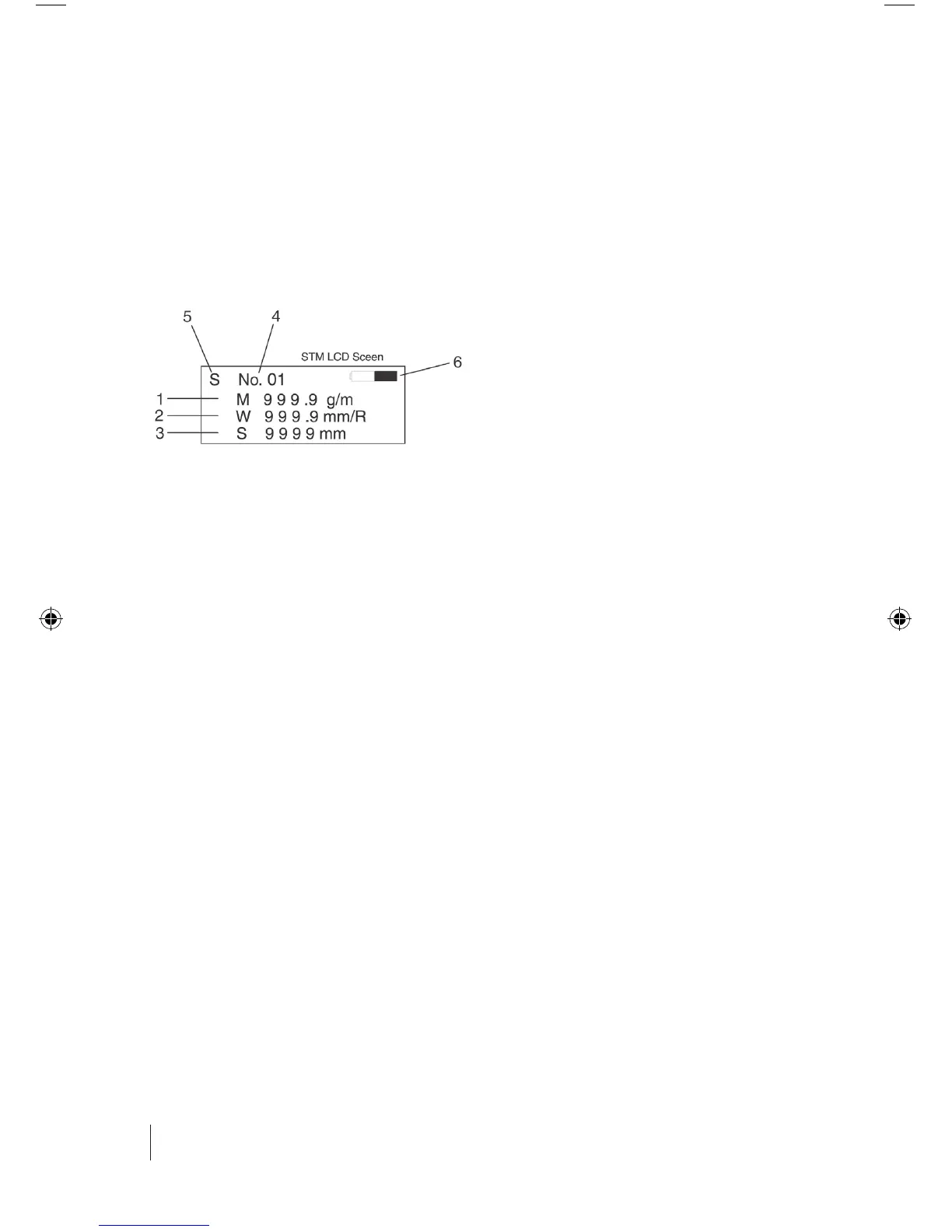
The opening screen displays the contents of the data storage register
that was last being used when the STM was turned off. Values for (1)
“MASS” (Belt Mass Constant), (2) “WIDTH” (Belt Width), and (3) “SPAN”
(Belt Span Length) are all displayed simultaneously.
Important Note: Reasonable non-zero belt constant values must
be used in the storage registers in order to receive belt tension readings.
The unit will display span frequency values regardless of the belt
constants entered, but will display “Error” and the red light will remain
on if the calculated belt tension value is beyond the display range of the
screen.
Pointer (4) indicates the data storage register number where current belt
data is saved. To change the data or storage register number, refer to
“Input Data Storage and Retrieval” on page 6.
Pointer (5) represents the current frequency filter setting. To change,
refer to “Frequency Filter Settings” on page 6.
Pointer (6) indicates the battery level meter. A dark battery symbol
indicates a full charge. When the battery level becomes critically low, the
meter indicator as well as a “Low Batt” message both blink.
1
2
3