14
Gates Corporation
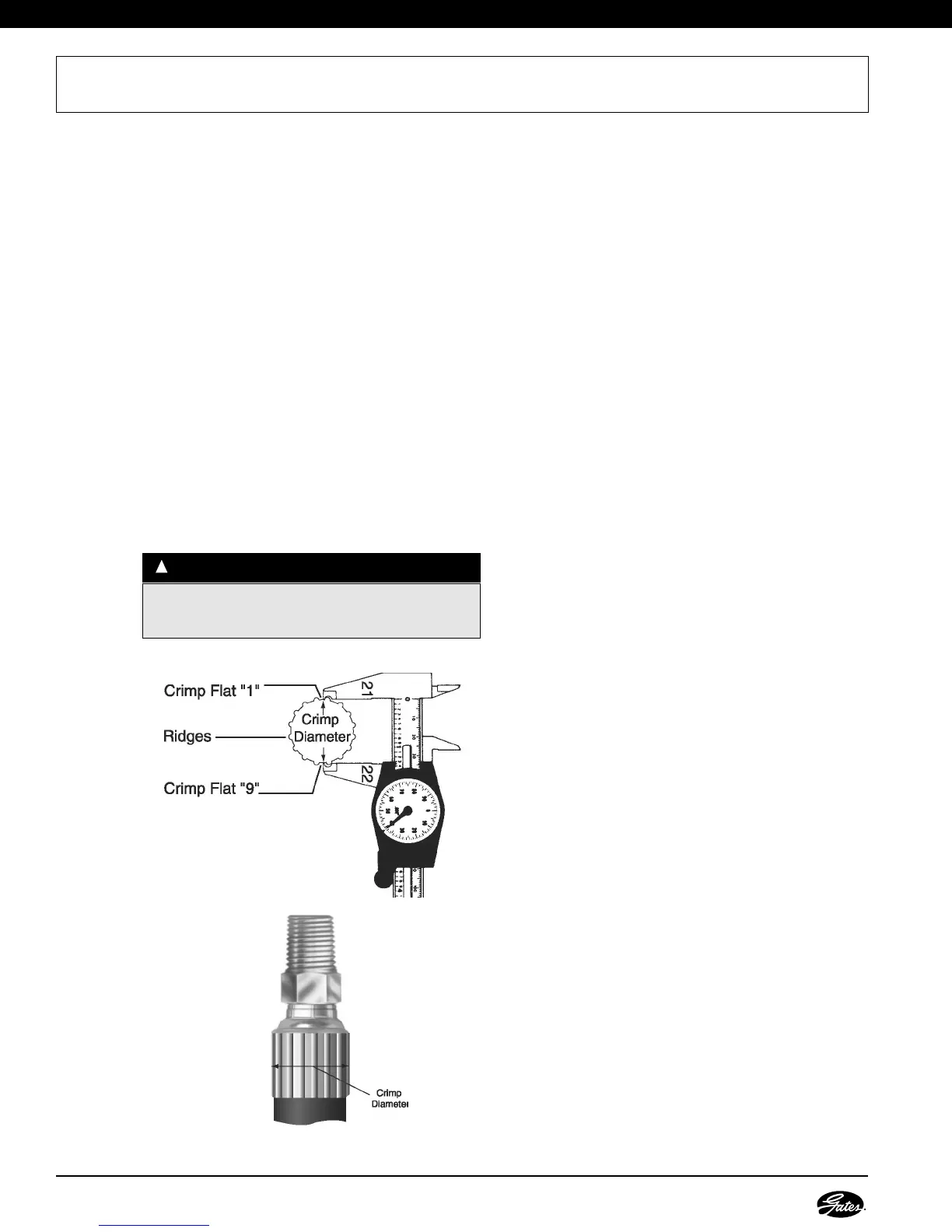
NOTE: DO NOT measure on top of part number
stamps or ridges.
1. Measure crimp diameter.
• Using Gates calipers (Product No. 7369-1320/
Part No. 78217), measure halfway between
ridges. (Fig. 1) To be sure crimp diameter is being
properly measured, mark a crimp flat. Beginning
with that flat, count 9 flats to get the diameter. Be
sure caliper fingers DO NOT touch ridges or part
number stamps.
• Measure halfway between the ends of the
crimped portion of the ferrule. (Fig. 2)
2. Check crimp diameter.
• The measured crimp diameter must be within
0.010" of the published crimp diameter.
• Should the actual crimp diameter not be within
specified crimp tolerance, the assembly MUST
be discarded.
MEASURING AND ADJUSTING CRIMP DIAMETERS
WWAARRNNIINNGG
::
Protect the safety of people using your assemblies!
Your measured crimp diameters MUST be in tolerance
range as listed in the Gates Crimp Data Manual.
!
3. Adjust the crimp diameter (if necessary).
• If crimp diameter is not within specified crimp
tolerance, an adjustment to the crimp setting
needs to be made.
• To obtain a smaller crimp diameter, change dial
vernier setting to a smaller number.
• To get a larger crimp diameter, change dial
vernier setting to a larger number. Changing the
dial vernier number by approximately .02 will
change crimp diameter .001".
• After the correct diameter is achieved, record this
new setting in your crimp data manual for future
reference.
4. Multiple crimps.
• When crimping multiple assemblies, check every
tenth crimp to ensure diameter is within accept
able range (± 0.010").
• Discard those outside the specified tolerance.