MC2000 USER GUIDE
7
Operating Principle
The kinematic crimping principle consists of transforming a rectilinear displacement, i.e.
that of the piston (8), into a radial displacement thus ensuring the crimping process by way
of the dies (7).
Mechanical bonding is achieved through the friction on a slope and a face on the barrel
clamp (3) and a slope (cone) on the piston (8) and the die holders (4). The die holders are
kept together during their travel by means of a spring arrangement.
The main components are made of a special steel and have been subjected to a series of
thermal body and surface treatments, so that they can resist the large loads and wear
through friction is prevented.
Precise guiding is ensured by means of two Teflon-Bronze bearers on the piston (14 & 17).
The piston is sealed by means of two O-rings + anti-extrusion bushes (15 & 16)
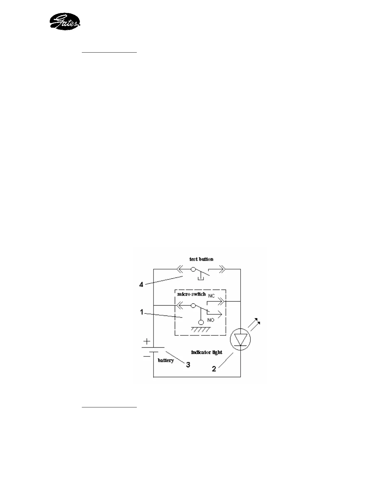
2. 3. 3 - THE ELECTRICAL SYSTEM
This system provides the supply power for the end-of-crimping indicator light
It comprises the following elements (see figure 3) :
- a micro-switch (1) - a 9V battery type 6 LR 61 (3)
- a red indicator light (2) - a test push-button (4)
Figure 3 : Electrical diagram
Operating Principle
This system indicates to the operator, by way of a light signal, that the set value on the
micrometer gauge has been reached, i.e. that the final crimping diameter has been attained.