Page 5-1
640t – Installation and Operating Instructions
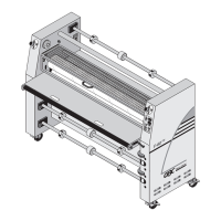
fi l m sh a f t s
Fig. 5-2 Take-up and Supply Shafts.
A. Release Liner Take-up
Rewinds the release liner of pressure sensitive lms.
It consists of a shaft, core adapters, and cardboard
core.
B. Upper Unwind/Supply Shaft
Holds the upper medium supply on the laminator.
C. Lower Unwind/Supply Shaft
Holds the lower medium supply on the laminator.
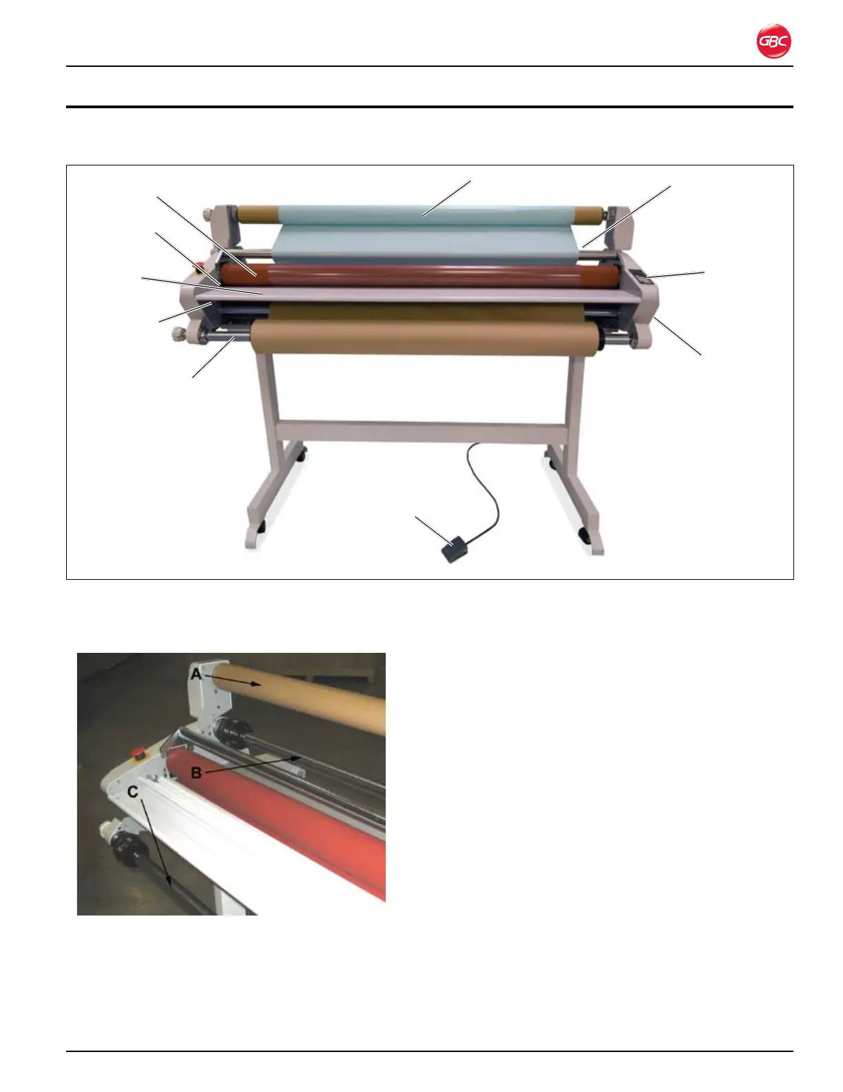
5. fe a t u r e g u i d e
Fig. 5-1. Laminator Identication.
This chapter helps you identify the main components of the laminator.
Bottom supply shaft
Control panel
Safety sensor
Feed table
Top lm supply shaft
Release liner take-up
Roller pressure
handle
Feed table
interlock latch
(under table)
Pressure roller
Foot switch