Do you have a question about the GE Multilin 469 and is the answer not in the manual?
Safety warnings and precautions for relay installation and use.
Guidance on navigating the relay's menu structure and understanding display messages.
Settings for motor protection during starting and normal operation.
Procedures for installing the relay unit and its case.
Introduction to the 469 Motor Management Relay and its integrated functions.
Detailed specifications for inputs, outputs, protection, and more.
Specifications for analog, differential, digital, ground, and phase current inputs.
Specifications for analog current output and assignable outputs.
Specifications for various protection elements like acceleration timer and current unbalance.
Specifications for digital counter and general purpose switch inputs.
Specifications for demand, reactive energy, and real energy monitoring.
Overview of relay packaging, drawout unit, and fixed case.
Procedures for installing the relay case in a standard 19-inch rack.
Steps to safely remove and insert the relay unit from its case.
Detailed list of all relay terminals and their functions.
Diagram illustrating typical wiring connections for the relay.
Connecting and ensuring compatibility of control power supply.
Configuration of phase CT inputs, including primary and secondary ratings.
Connection of AC voltage inputs, including VT ratio and open delta/wye configurations.
Connecting digital inputs for dry contact and avoiding EMI issues.
Connecting analog current input signals and power supply.
Configuring analog output channels for various measured parameters.
Connecting RTD inputs for temperature monitoring.
Details on the six Form-C output relays and their failsafe/non-failsafe nature.
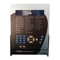
Overview of the front panel interface including display, LEDs, and keys.
Explanation of 469 Status, Motor Status, and Output Relay LED indicators.
Procedure for accessing and altering settings, including passcode and access jumper.
Explanation of self-test diagnostics and warning messages.
Introduction to the EnerVista 469 Setup software GUI and its capabilities.
Typical connection methods for RS232, RS485, and Ethernet communications.
Minimum system requirements and installation procedure for EnerVista software.
Steps to configure serial communications for RS232, RS485, or Ethernet.
Illustrates entering current sensing settings via the software interface.
Procedure to update settings files to match new firmware revisions.
Procedure for loading settings files into the relay.
Procedures for upgrading the 469 firmware with new files.
Capturing and viewing waveforms from the relay at trip instances.
Viewing real-time relay data via the main window menu.
Installing and using EnerVista Viewpoint for critical 469 information access.
Basic categories of protection elements: trips, alarms, and blocks.
Features and procedures for passcode access security.
Settings for serial communication ports, baud rates, and parity.
Settings for phase CT primary, motor FLA, and ground CT primary.
Settings for VT connection type, ratio, and motor nameplate voltage.
Overview of digital inputs, access switch, test switch, and emergency restart.
Overview of the six output relays and their failsafe/non-failsafe nature.
Forcing output relays in static or dynamic mode for testing.
Principles of motor thermal limits and manufacturer data requirements.
Primary protective function of the 469, including overload curve and pickup settings.
Setting up overload curves: Standard, Custom, or Voltage Dependent.
Feature for short circuit protection, including pickup, delay, and backup.
Settings for ground fault protection, including alarm, trip, and backup.
Settings for phase differential protection elements.
Procedures for performing functional tests of hardware and firmware interaction.
Verifying phase current accuracy by injecting known current values.
Verifying phase current accuracy by injecting known current values.
Verifying voltage input accuracy by applying known voltage values.
Verifying accuracy of ground and differential current inputs.
Verifying the functionality of the output relays by forcing their operation.
Verifying overload curve timing accuracy and pickup.
Verifying overload curve timing accuracy and pickup.
Verifying the performance of the short circuit element timing and pickup.
General Electric Multilin warranty terms for devices.
| Frequency | 50/60 Hz |
|---|---|
| Digital Inputs | 8 |
| Mounting | Panel Mount |
| Display | LCD |
| AC Voltage Input | 100-240V AC |
| Current Rating | 5A |
| Communication Protocols | Modbus RTU, Modbus TCP/IP |
| Protection Functions | Overcurrent |
| Operating Temperature | -20°C to +70°C |
| Inputs | Digital |
| Outputs | Relay Outputs |