2 MM200 MOTOR MANAGEMENT SYSTEM – QUICKSTART GUIDE
OVERVIEW QUICKSTART GUIDE
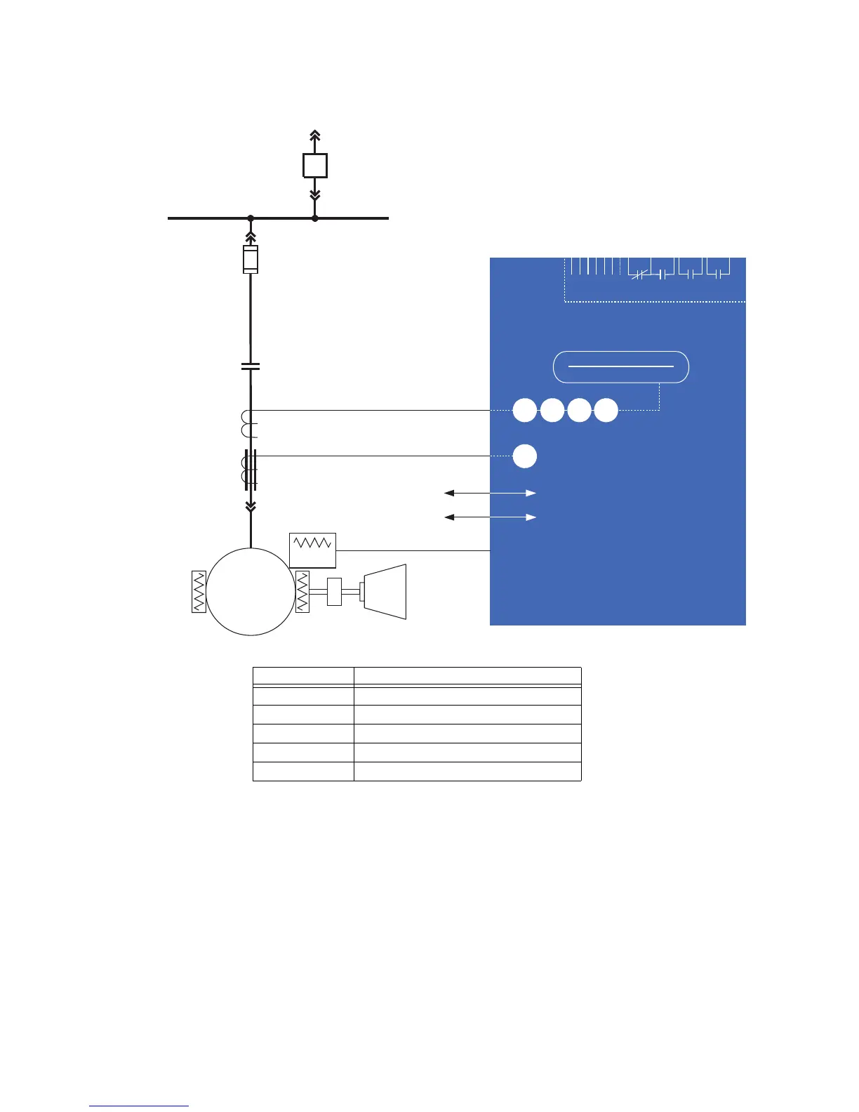
Figure 1: Single line diagram
Table 1: MM200 protection functions
1.1.1 Mechanical installation
This section describes the mechanical installation of the MM200 system, including
dimensions for mounting.
1.1.1.1 Dimensions
The MM200 is packaged in a fixed format divided into three specific sections.
The dimensions of the MM200 are shown below. Additional dimensions for mounting are
shown in the following sections.
RS485 - Modbus RTU
Profibus/DeviceNet
52
METERING
A
51R
49
37
46
50G
MOTOR
LOAD
Temperature
Thermistor
Phase CT 3
Ground CT 1
Power Fuse
BUS
MM200
MOTOR MANAGEMENT SYSTEM
Contactor
888739A2.CDR
LO: 7 inputs and 3 outputs
HI: 6 inputs and 3 outputs
LO:24VDC
HI:84to250VDC/60to300VAC
ANSI device Description
37 Undercurrent and underpower
46 Current unbalance
49 Thermal overload
50G Ground instantaneous overcurrent
51R Locked/stalled rotor, mechanical jam
 Loading...