SPECIFICATIONS
Input Voltage: 120 VAC, 208/240 VAC, or 277 VAC in all units based
upon dipswitch configuration.
15252 NEMA 3R Indoor & Outdoor BM-A301US5-O2
15253, 15251 NEMA 1 Indoor BM-A301US5-I2
15250 NEMA 3R Indoor & Outdoor EM-A301US9-O2
Switch Rating: DPDT Models
Normally Open Contacts
40A Resistive, 120-277Vac.
30A General Purpose, 120-277Vac.
20A Resistive, 30Vdc
1 HP, 120Vac ; 2HP, 240Vac
20A Ballast, 120-277Vac.
15A Tungsten, 120Vac
800VA, Pilot Duty, 120Vac.
720VA, Pilot Duty, 240Vac.
TV-5, 120Vac
Normally Closed Contacts
30A Resistive, 120-277Vac
15A General Purpose, 120-277Vac
15A Resistive, 30Vdc
20A Ballast, 120-277Vac
1/4HP, 120Vac; 1/2HP, 208-240Vac.
290VA, Pilot, 120Vac.
360VA, Pilot, 208-240Vac.
NOTE: If loads are connected to both NC and NO contacts, both contacts are
derated to 67% of the above values.
ENVIRONMENTAL RATINGS
Ambient Temperature: –40F to 130F
Humidity: 0-95% RH, Non-condensing
WIRING CONNECTIONS
Screw clamp terminals for up to 2 AWG #8 wires per position. For supply
connections, use 8AWG or larger wires suitable for at least 105° C. Use copper
conductors only.
LIGHTS
Power LED (Orange) – Light illuminates when power is applied to
the timer
Status LED (Green) – Light illuminates when power is applied to load.
INSTALLATION
CAUTION: Before wiring or service, power to this time switch and the
equipment it controls must be turned off. Turning off the timer switch only
will not prevent a shock hazard. Replace cover plate within housing before
supplying power to time switch. Installation should be performed by a licensed
electrician only. Before installing this product read all instructions carefully.
Remove protective cover panel within time switch housing by removing
screws located above timer face and at the bottom of the cover panel.
DIPSWITCH CONFIGURATION
WARNING: Failure to properly configure the dipswitch will result in
damage to the unit and void the warranty! Before installing and wiring the GE
Time Switch, proper configuration must be selected. This is accomplished as
follows:
INPUT VOLTAGE DIP SWITCH SETTING:
1. Do not apply power to the timer prior to setting correct Input Voltage DIP
switch.
2. Determine the input voltage which will be applied to the timer (i.e. L1 and
L2/N terminals, see wiring diagrams)
3. Set the DIP switch according to the diagram below.
NOTE: Unit is shipped with DIP switches set for 277VAC Input Voltage
CAUTION: Do not check circuits by “sparking” wires to terminals. Damage to
the timer may result.
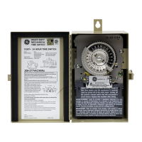
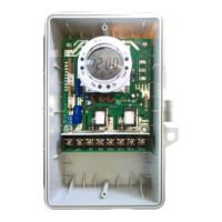
Digital Time Switch
15250
Indoor/Outdoor
NEMA 3R-Rated
Enclosure
NOTE: For outdoor locations (model GE 15252),, rain tight or wet location
conduit hubs that comply with requirements of UL 514B (standard for fittings
for conduit and outlet boxes) must be used.
1. Remove 2 screws retaining the interior cover panel and remove panel
by prying out with a thin blade at the top.. Select knockouts to be used.
Remove the inner 1/2” knockout by inserting a screwdriver in the slot
and carefully punch knockout loose. Remove slug. If the 3/4” knockout
is required, remove the outer ring with pliers after removing the 1/2”
knockout. Smooth edges with knife if necessary.
2. Place enclosure in desired mounting location and mark the three
mounting holes.
3. Drill holes for #10 screws, start screws in holes.
4. Place enclosure over screws and tighten screws.
5. Connect conduit hubs to conduit before connecting the hubs to the
enclosure. After inserting hubs into enclosure, carefully tighten hub lock
nut. Do not over-tighten.
6. Install in accordance with all applicable National and Local code
requirements. See Figure 1 and wiring diagrams.
7. Replace interior cover panel and 2 screws.
GROUNDING: This enclosure is of plastic construction and does not
require a ground connection and does not require bonding in pool
applications.
This enclosure does not provide grounding between conduits. When using
non-metallic conduit or cable, connect the ground wires of all cables together
with a wire nut. When metallic conduit is used, use grounding type bushings
and a jumper wire between each conduit.
120VAC
277VAC (Default)
208~240VAC
NOTE: Unit is shipped with DIP Switches set for 277VAC Input Voltage.
CAUTION: Do not check circuits by “sparking” wires to terminals. Damage to
the timer may result.
INPUT VOLTAGE DIP SWITCH SETTING:
1. Do not apply power to the timer prior to setting correct Input Voltage DIP switch.
2. Determine the input voltage which will be applied to the timer (i.e. L1 and L2/N terminals,
see wiring diagrams).
3. Set the DIP Switch according to the diagram below.