Do you have a question about the GE POWER/VAC 13.8 and is the answer not in the manual?
All servicing of switchgear must be performed by trained personnel with primary and control power circuits de-energized.
Defines metal-clad switchgear and emphasizes thorough instruction and supervision for personnel.
Procedures for safe receiving, handling, and storage of metal-clad switchgear equipment.
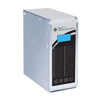
Describes the front enclosure containing instruments, control, and protective devices.
Contains high voltage equipment like breaker compartments, bus, and cable termination spaces.
Details the removable circuit breaker unit, its features, and interchangeability.
Explains the purpose and function of the lift truck used for breaker handling.
Explains the mechanism for moving the breaker between connected and test positions.
Describes the optional electrically operated device for racking breakers remotely.
Details the 1200 and 2000 ampere primary disconnects and their construction.
Describes the insulated metal compartment housing the main bus bars.
Details the location and access to current transformers behind shutter barriers.
Space for connecting primary cables via potheads or terminals, with NEMA drilling.
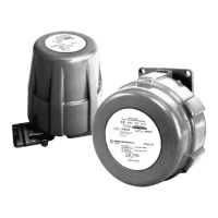
Describes voltage transformers mounted on an auxiliary unit with safety features.
Explains the use of fuses for protecting circuits where breakers are not cost-effective.
Describes dummy elements used for isolating circuits where frequent operation is not needed.
Device for making primary conductors accessible for grounding, testing, and phasing.
Specifies recommended aisle space requirements for front and rear equipment access.
Details indoor and outdoor anchoring methods and floor preparation requirements.
Guidance on ensuring a strong, level floor to withstand switchgear weight and impact loads.
Instructions for concrete or reinforced concrete foundations and anchoring for outdoor units.
Step-by-step procedures for installing outdoor switchgear with a protected aisle.
Step-by-step procedures for installing outdoor switchgear with a common aisle.
Describes the test cabinet used for operating breakers removed from switchgear.
Procedures for adding new units to existing switchgear line-ups.
Detailed steps for adding new metal-clad units to protected or common aisle configurations.
Detailed steps for adding new metal-clad units to outdoor switchgear without an aisle.
Guidance on applying specific greases to contact surfaces for optimal performance.
Details procedures for cleaning and greasing sliding connection contact surfaces.
Specifies torque values for various bolt sizes used in switchgear assembly.
Procedure for assembling the main bus at shipping splits or when adding new units.
Instructions for applying insulating tape to bus bars and joints for 5kV and 15kV equipment.
Details bus bar dimensions and taping procedures for insulation.
Instructions for insulating dead end bus joints.
Instructions for insulating bus connection joints.
Instructions for insulating current transformer joints.
Instructions for insulating tee connection joints.
Instructions for insulating double bus bar joints.
Instructions for insulating potheads, bushings, or terminators.
Instructions for insulating #6 cable termination joints.
Instructions for gasket installation on outdoor bus ducts.
Step-by-step guide for installing primary cables into switchgear units.
Method for terminating single conductor cables without using potheads.
Guidelines for insulating primary cable terminations following specific procedures.
Details installation procedures for potheads used for cable terminations.
Discusses methods and kits for terminating cables without using potheads.
Describes through-type current transformers for sensitive ground fault protection.
Instructions for routing and connecting control cables into switchgear units.
Details the connection and importance of the ground bus for safety.
Purchaser's responsibility to specify surge arresters for lightning protection.
General Electric surge suppressors provided on each feeder circuit.
Instructions for applying insulation to roof entrance bushings.
Steps for safely installing and removing circuit breakers from the switchgear.
Details the components and function of the breaker racking mechanism.
Illustrates how to connect the lift truck to the switchgear rails for breaker handling.
Describes the indicator lever that shows the position of the breaker racking arm.
Procedure for racking breakers with the front door closed for safety.
Details the electrical attachment for remote breaker racking operations.
Explains the positive interlock preventing unsafe breaker racking positions.
Describes the negative interlock that holds the breaker in a trip-free mode.
Explains the interlock preventing charging breaker springs unless in correct position.
Details the use of key locks and padlocks for breaker racking and operation control.
Interlock ensuring only breakers with matching ratings are inserted.
Interlock preventing racking if the spring-blocking device is in the gagged position.
Describes the auxiliary switch actuated by breaker operation.
Details the switch indicating the breaker's 'Connect' position.
Information on space heaters provided in outdoor equipment for temperature control.
Outlines essential maintenance tasks for switchgear structure and connections.
Describes the acrylic paint finish used on switchgear for durability and aesthetics.
Procedures for refinishing or repairing the acrylic paint finish on switchgear.
Guidelines for specifying and ordering renewal parts from Switchgear Operations.