140 469 MOTOR MANAGEMENT RELAY – COMMUNICATIONS GUIDE
DEVICENET PROTOCOL COMMUNICATIONS GUIDE
DeviceNet Data Formats
DeviceNet also uses the same format codes specified in Modbus Memory Map. Consult the
Modbus memory map for additional details on the output messages.
The DeviceNet specific Format codes are as follows:
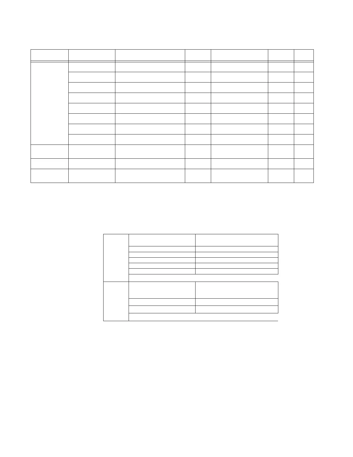
20h ANALOG
INPUT MAXIMUMS
& MINIMUMS
1 to 4 (low,high) Analog input 1 minimum 32bits 0, -50000, 50000 -- F12
5 to 8 (low,high) Analog input 1 maximum 32bits 0, -50000, 50000 -- F12
9 to 12 (low,high) Analog input 2 minimum 32bits 0, -50000, 50000 -- F12
13 to 16 (low,high) Analog input 2 maximum 32bits 0, -50000, 50000 -- F12
17 to 20 (low,high) Analog input 3 minimum 32bits 0, -50000, 50000 -- F12
21 to 24 (low,high) Analog input 3 maximum 32bits 0, -50000, 50000 -- F12
25 to 28 (low,high) Analog input 4 minimum 32bits 0, -50000, 50000 -- F12
29 to 32 (low,high) Analog input 4 maximum 32bits 0, -50000, 50000 -- F12
21h MOTOR
THERMAL
CAPACITY USED
1,2 (low,high) Motor thermal capacity used 16bits 0, 0, 100 % F1
22h TIME TO TRIP 1 to 4 (low,high) Time to trip 32bits –1, –1, 99999 s F20
23h CONTAIN
ATTRIBUTES 01h to
10h
248bytes All attributes 01h to 10h together 248bytes N/A N/A N/A
Table 28: Data formats for class B0h, Instance 01h:
Attribute Bytes Description Length Default, Min, Max Value/Unit
Format
Code
F160 Unsigned 8 bit integer ALARM STATUS
0 Off
1 Not Active
2 Timing Out
3 Active
4 Latched
F161 Unsigned 8 bit integer MOTOR SPEED
0 Low Speed (Speed 1)
1 High Speed (Speed 2)

 Loading...


