489 GENERATOR MANAGEMENT RELAY – COMMUNICATIONS GUIDE 51
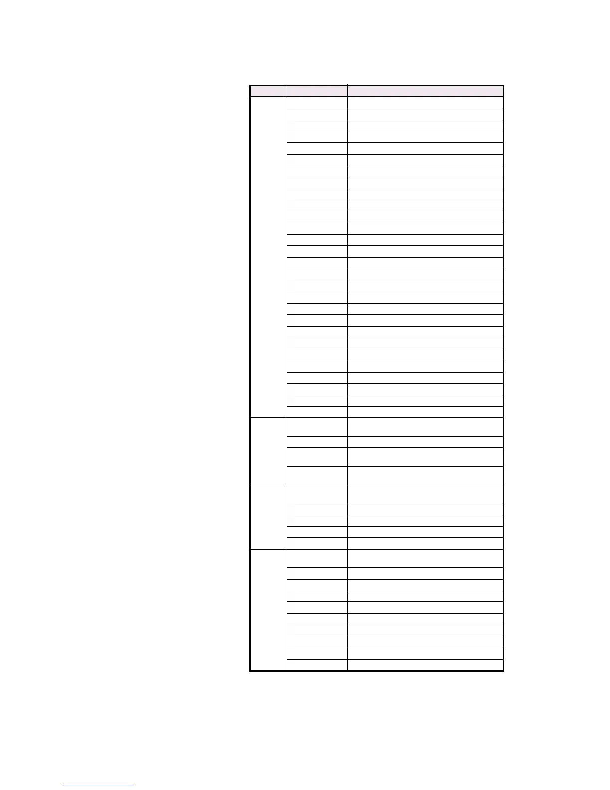
F134
ctd.
114 Volts/Hertz Trip
115 Volts/Hertz Alarm
116 Low Forward Power Trip
117 Inadvertent Energization
118 Serial Start Command
119 Serial Stop Command
120 Input A Control
121 Input B Control
122 Input C Control
123 Input D Control
124 Input E Control
125 Input F Control
126 Input G Control
127 Neutral Overvoltage Alarm
128 Neutral Undervoltage (3rd Harmonic) Alarm
129 Setpoint Group 1 Active
130 Setpoint Group 2 Active
131 Loss of Excitation 1
132 Loss of Excitation 2
133 Ground Directional Trip
134 Ground Directional Alarm
135 High-Set Phase Overcurrent Trip
136 Distance Zone 1 Trip
137 Distance Zone 2 Trip
138 Digital Input Waveform Trigger
139 Serial Waveform Trigger
140 IRIG-B Failure
141 Running Hours Alarm
F136
Unsigned
16 bit integer
ORDER CODE
Bit 0 0 = P5 (5 A CT secondary), 1 = P1 (1 A CT secondary)
Bit 1
0 = HI (High Voltage Power Supply),
1 = LO (Low Voltage Power Supply)
Bit 2
0 = A20 (4 to 20 mA Analog Outputs),
1 = A1 (0 to 1 mA Analog Outputs)
F138
Unsigned
16 bit integer
SIMULATION MODE
0Off
1 Simulate Pre-Fault
2 Simulate Fault
3Pre-Fault to Fault
F139
Unsigned
16 bit integer
FORCE OPERATION OF RELAYS
0 Disabled
11 TRIP
22 AUXILIARY
33 AUXILIARY
44 AUXILIARY
55 ALARM
66 SERVICE
7All Relays
8No Relays
Table CG–2: Data Formats (Sheet 10 of 14)
CODE TYPE DEFINITION

 Loading...


