52 489 GENERATOR MANAGEMENT RELAY – COMMUNICATIONS GUIDE
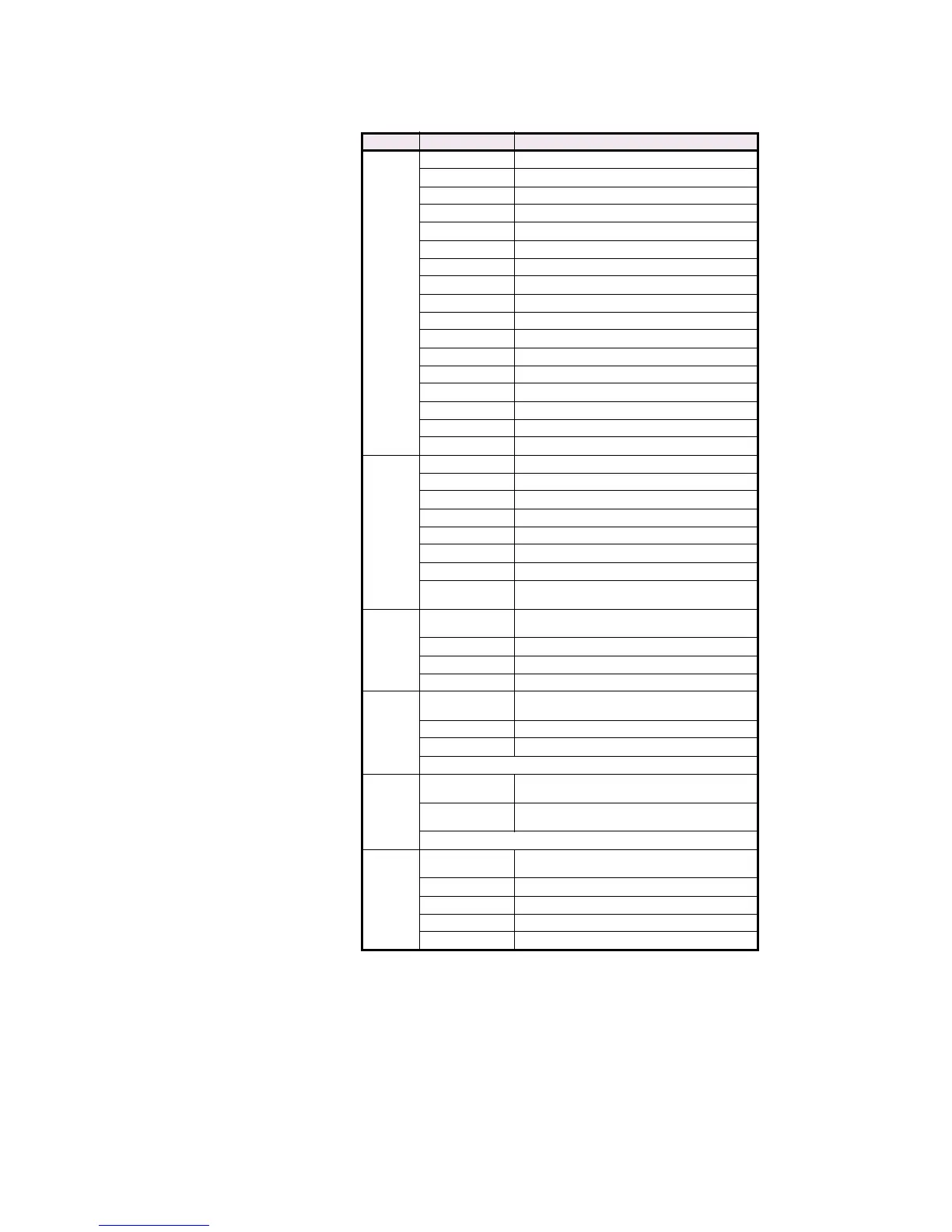
F140
16 bits GENERAL STATUS
bit 0 Relay in Service
bit 1 Active Trip Condition
bit 2 Active Alarm Condition
bit 3 Reserved
bit 4 Reserved
bit 5 Reserved
bit 6 Reserved
bit 7 Simulation Mode Enabled
bit 8 Breaker Open LED
bit 9 Breaker Closed LED
bit 10 Hot Stator LED
bit 11 Negative Sequence LED
bit 12 Ground LED
bit 13 Loss of Field LED
bit 14 VT Failure LED
bit 15 Breaker Failure LED
F141
16 bits OUTPUT RELAY STATUS
bit 0 1 TRIP
bit 1 2 AUXILIARY
bit 2 3 AUXILIARY
bit 3 4 AUXILIARY
bit 4 5 ALARM
bit 5 6 SERVICE
bit 6 to
bit 15
Not Used
F142
Unsigned
16 bit integer
THERMAL MODEL CURVE STYLE SELECTION
0Standard
1Custom
2 Voltage Dependent
F148
Unsigned
32 bits integer
1st 16 bits High Order Word - Long.
2nd 16 bits Low Order Word - Long.
For example: 123456 stored as 1st word: 0001 hex, 2nd word: E240 hex.
F150
Unsigned
32 bits integer
IP ADDRESS / SUBNET MASK / DEFAULT GATEWAY
Each byte in this register represents one octet in
the IP Address.
For example: 0x015EDA1F means 1.94.218.31
F152
Unsigned
16 bit integer
ETHERNET STATUS
0 Diagnostic Status On
1 Connection Status On
2Not Used
3 Ethernet Link Status On
Table CG–2: Data Formats (Sheet 11 of 14)
CODE TYPE DEFINITION

 Loading...


