CHAPTER 1: INTRODUCTION DESCRIPTION OF THE 869 MOTOR PROTECTION SYSTEM
869 MOTOR PROTECTION SYSTEM – INSTRUCTION MANUAL 1–3
current and voltage phasors, such that the resulting values have no harmonic
components. RMS (root mean square) values are calculated from one cycle of samples
prior to filtering.
Protection Elements
All voltage, current and frequency protection elements are processed eight times every
cycle to determine if a pickup has occurred or a timer has expired. The voltage and current
protection elements use RMS current/voltage, or the magnitude of the phasor.
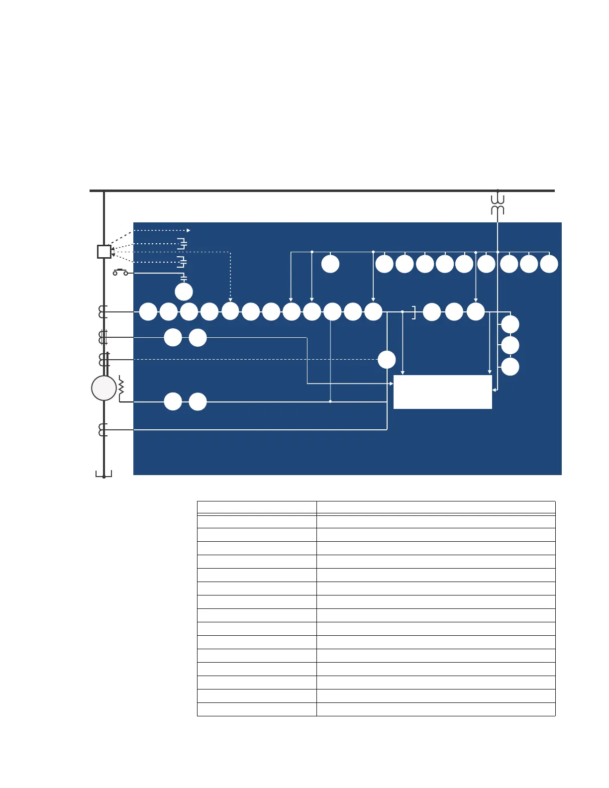
Figure 1-1: Single Line Diagram
Table 1-1: ANSI Device Numbers and Functions
892825A4.CDR
Phase CT
RTD
27P
59P 59N
59_2
VTFF 81U 81O
87S
METERING
TRANSIENT RECORDER
EVENT RECORDER
FAULT REPORT
TRIP
52
CLOSE
MONITORING
50BF
51P
50P
67P
50_2
50LR
49
BUS
Breaker
32
869
Motor Protection System
Neutral CT
M
50G/N51G/N
67N
86
55
START
3
3
Ground CT
1
Differential
core
balance CT
3
37
47
50G
51G
Internal Summation Percent Differential
Core Balance Percent Differential
81R
40
40Q
78
24
66
38
49S
AFP
27P
LIGHT
ANSI Device Description
12/14 Over Speed Protection/ Under Speed Protection
24 Volts per Hertz
27P Phase Undervoltage
32 Directional Power
37 Undercurrent
37P Underpower
38 Bearing RTD Temperature
40 Loss of Excitation
40Q Reactive Power
46 Current Unbalance
47 Phase Reversal
49 Thermal Model
49S Stator RTD Temperature
50BF Breaker Failure
50G Ground Instantaneous Overcurrent