CHAPTER 3: INTERFACES SOFTWARE INTERFACE
889 GENERATOR PROTECTION SYSTEM – INSTRUCTION MANUAL 3–39
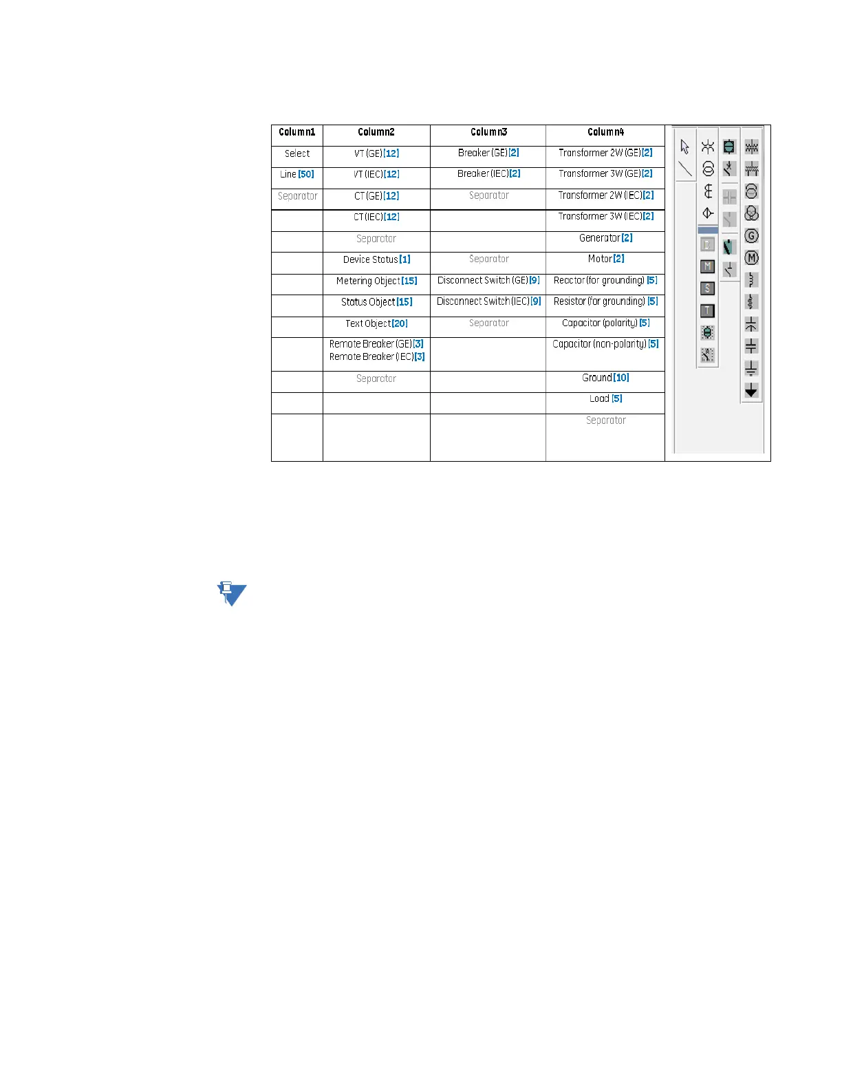
Figure 3-19: SLD Configurator Component Library
Control Objects
The control objects consist of selectable breakers and disconnect switches. The following
figure shows the different symbols in the GE Standard style and IEC style. If the switching
element is tagged, blocked, or bypassed, indicators with the letters “T”, “B”, and “By”
appear on the lower right corner of the element. Additionally, the breaker/switch name is
displayed on top of the object.
NOTE:
The displayed breaker name is configured in the setpoint Setpoints > System > Breakers >
Breaker[X] > Name. This setpoint has a 13-character limit. The name should be kept to a
minimum so that it appears properly on the SLD.