4–372 889 GENERATOR PROTECTION SYSTEM – INSTRUCTION MANUAL
FLEXLOGIC CHAPTER 4: SETPOINTS
FlexLogic
To provide maximum flexibility to the user, the arrangement of internal digital logic
combines fixed and user-programmed parameters. Logic upon which individual features
are designed is fixed, and all other logic, from digital input signals through elements or
combinations of elements to digital outputs, is variable. The user has complete control of
all variable logic through FlexLogic. In general, the system receives analog and digital
inputs, which then uses FlexLogic to produce analog and digital outputs.
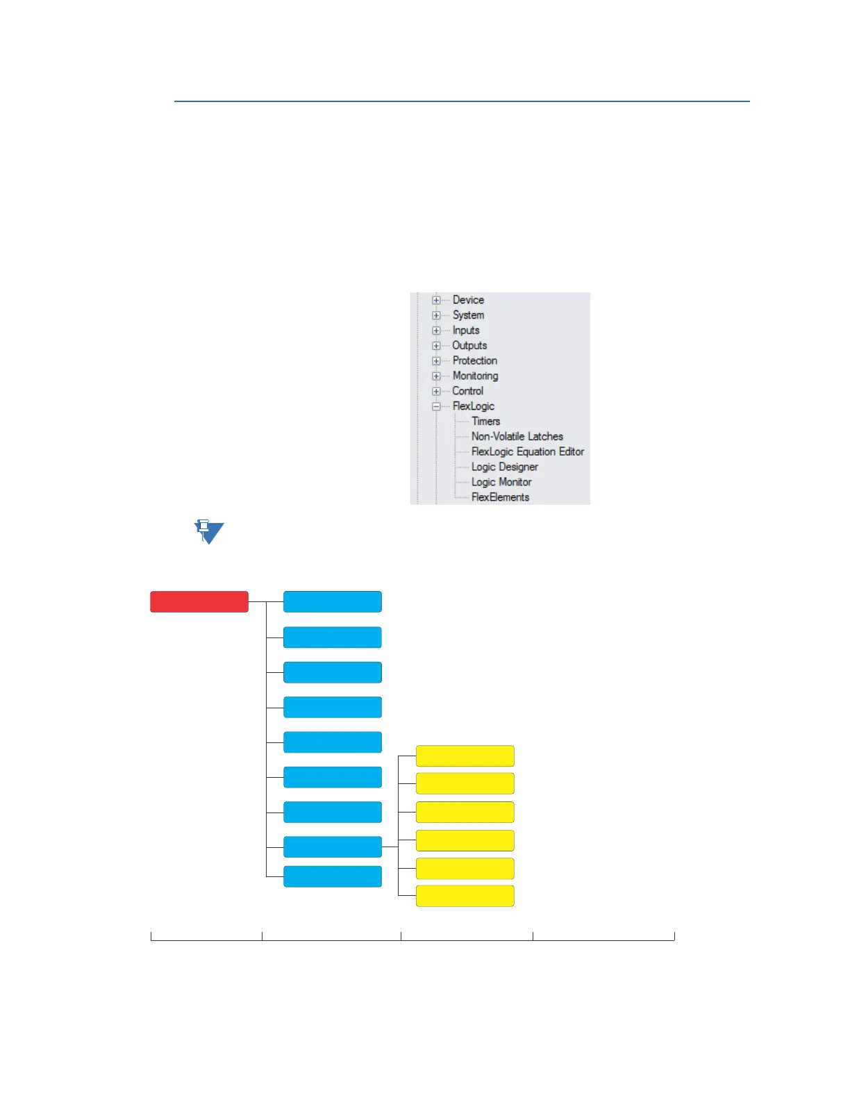
The major sub-systems of a generic 8-series relay involved in this process are shown as
follows.
NOTE:
For information on the Logic Designer and Logic Monitor menu items, see Help >
User Manual > Logic Designer & Monitor in the EnerVista 8 Series Setup software.
Figure 4-155: FlexLogic Display Hierarchy
The states of all digital signals used in the 889 are represented by flags (FlexLogic™
operands). A digital “1” is represented by a 'set' flag. Any external contact change-of-state
can be used to block an element from operating, as an input to a control feature in a
FlexElements
Logic Designer
Setpoints
Device
System
Inputs
Outputs
Protection
Monitoring
Control
FlexLogic
Non-Vol Latches
Timers
Level 1 Level 2 Level 3 Level 4
FlexLogic
Equation
T
M
Logic Monitor
Testing