CHAPTER 1: INTRODUCTION DESCRIPTION OF THE 889 GENERATOR PROTECTION SYSTEM
889 GENERATOR PROTECTION SYSTEM – INSTRUCTION MANUAL 1–3
current and voltage phasors, such that the resulting values have no harmonic
components. RMS (root mean square) values are calculated from one cycle of samples
prior to filtering.
Protection Elements
All voltage, current and frequency protection elements are processed eight times every
cycle to determine if a pickup has occurred or a timer has expired. The voltage and current
protection elements use RMS current/voltage, or the magnitude of the phasor.
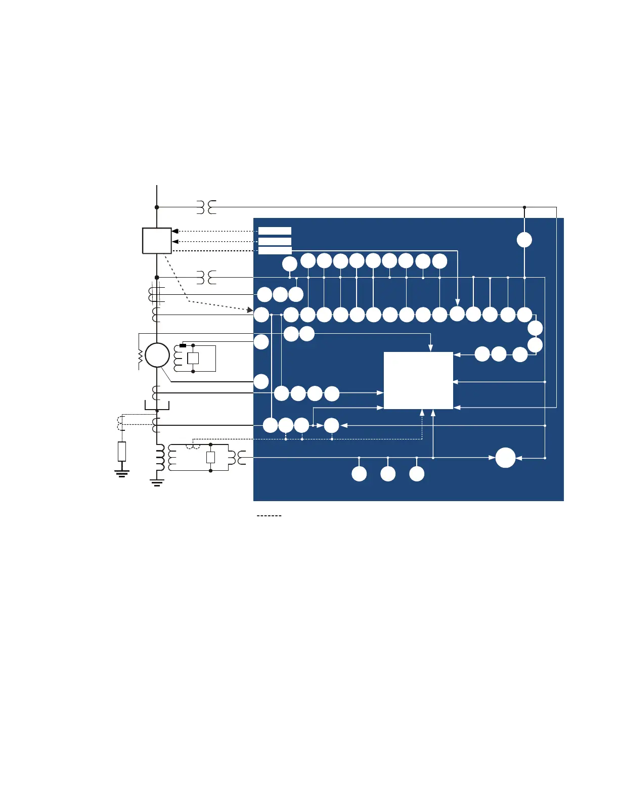
Figure 1-1: Single Line Diagram
894153A2.cdr
50G
87GD
51G
64TN
51V 51N46
67_2
78
24
59P27P
25
Metering
Transient Recorder
Event Recorder
Trip
Close
40
59N 81U81O
27TN
59X
52
R
87G
50N
81R
50P
G
49
EX
889 Generator Protection System
Slot J1 – Ph Bank
Slot K1 – Ph Bank
Slot J2 – Ph Bank
Slot J –Ground
Slot J – Vx
Slot K2 – Ph Bank or Vx
R
RTD
50/27
67G
59_2
40Q
Monitoring
50SG 51SG 67SG
32
Slot K – Ground
(Sensitive or 50:0.025)
50N50P
50_2
50_2
38
76
dcmA
50OL
39
dcmA
47
50OFL
81A
49TOL
VTFF
50BF
Alternatives for connection
27X
67P
67N
55
AFP
LIGHT