4–124 889 GENERATOR PROTECTION SYSTEM – INSTRUCTION MANUAL
PROTECTION CHAPTER 4: SETPOINTS
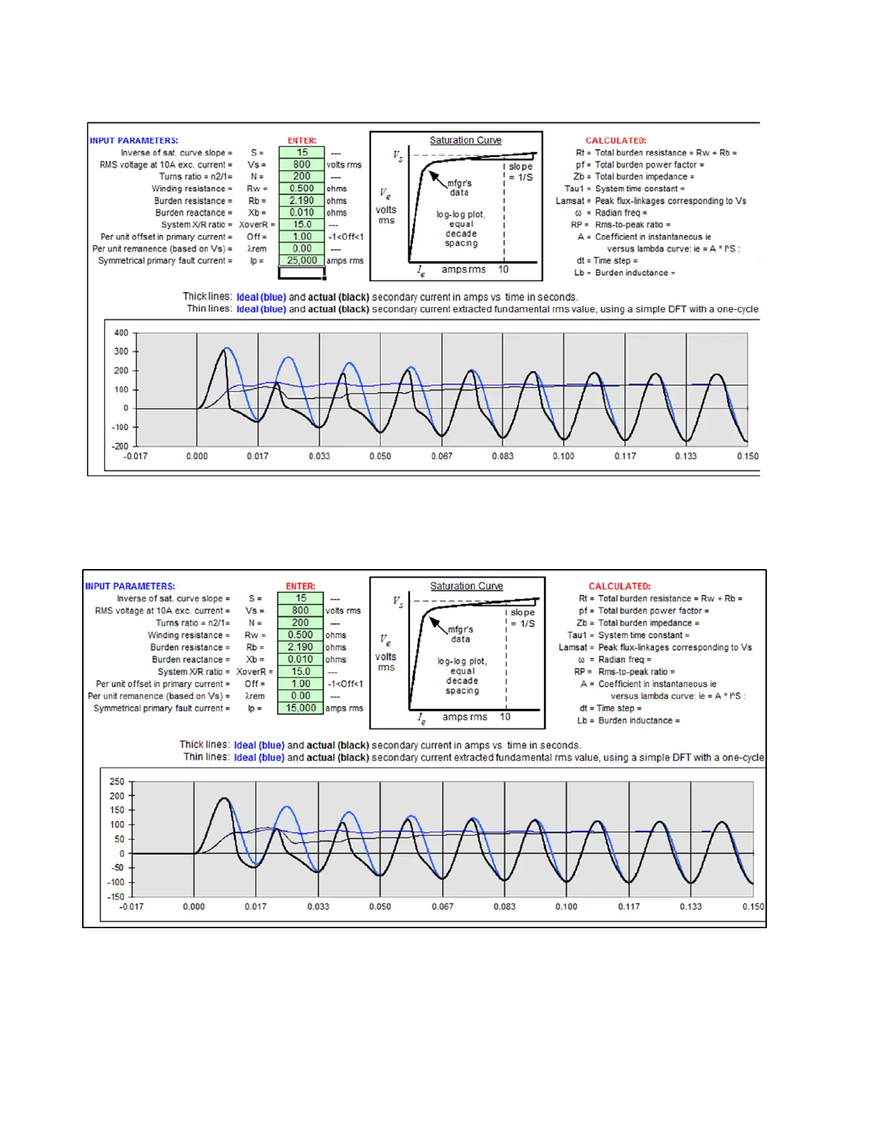
Logging this data into the CT sat tool, produces the following CT saturation waveform:
The waveform shows that during this external bolted fault with maximum fault current of
25 kA, the CT (3000:5) will saturate severely, and produce only a ¼ of a cycle saturation
free time. Break 2 must be set to a through fault current so that the CT (3000:5) produces at
least ½ cycle saturation free time. The solution is to change the fault current to 15000 kA.
The waveform now shows a bigger part of the first cycle before saturation.
The fault current of 15000 Amps would then be translated as 15000/3000 = 5 times
winding 2 CT. Bringing this to the same scale with respect to winding 1 CT reference , i.e.
multiplying by a magnitude of 0.4521, the Break 2 setting would be:
Break 2 = 5 *0.4521 = 2.21 xCT (w1)