4–278 889 GENERATOR PROTECTION SYSTEM – INSTRUCTION MANUAL
MONITORING CHAPTER 4: SETPOINTS
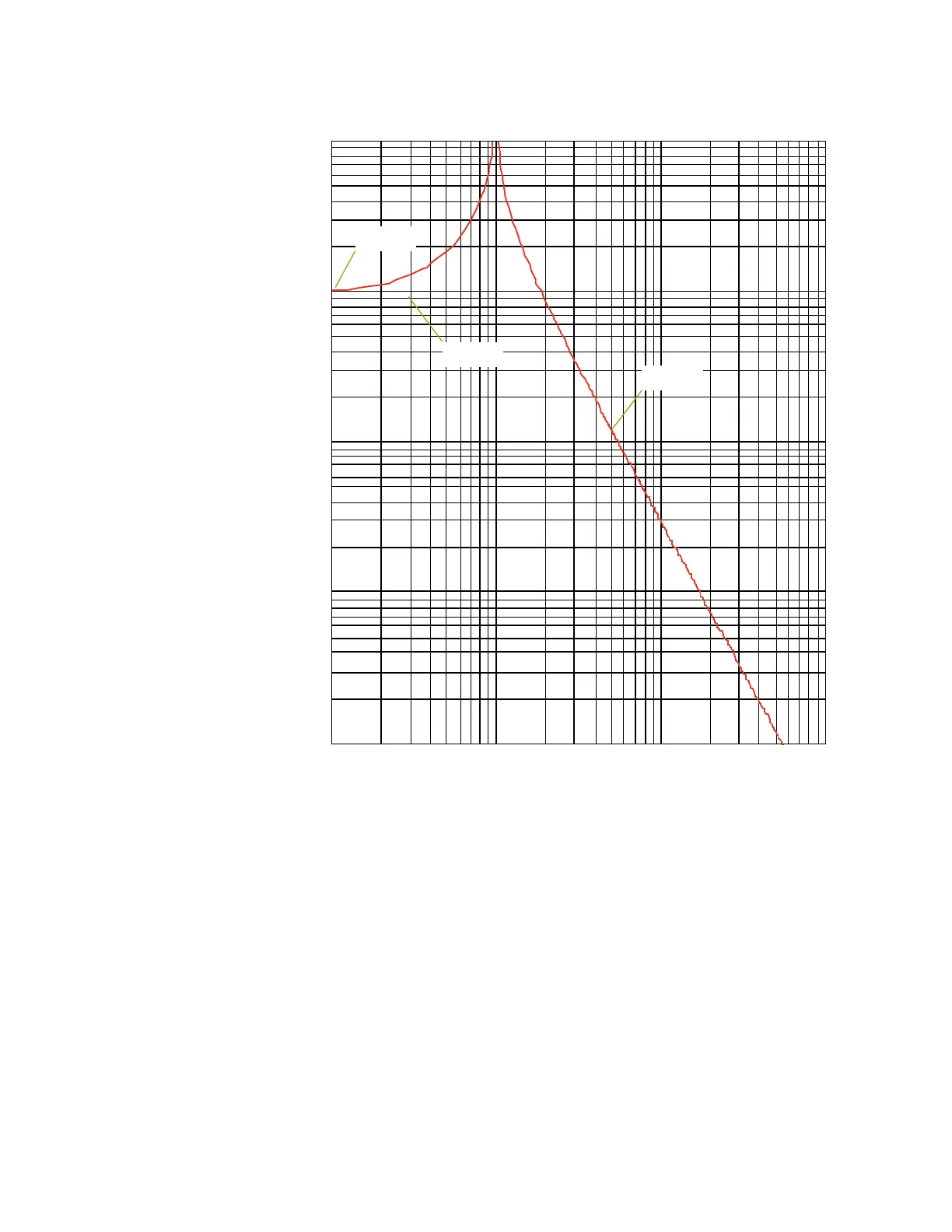
Figure 4-110: IEC 255-8 Sample Operate and Reset Curves
The thermal overload protection element removes the Thermal OP output operand when E
< 5%. In case of emergency, the thermal memory and Thermal OP output operand can be
reset using the FlexLogic operand programmed under the Thermal Reset setting.
All calculations are performed per phase. If the accumulated thermal capacity reaches a
value of 100% in any phase, the thermal overload protection element operates, and only
resets when thermal capacity is less than 5% in all three phases.
Path: Setpoints > Monitoring > Thermal Overload Protection
FUNCTION
Range: Disabled, Alarm, Latched Alarm, Configurable
Default: Disabled
This setting enables the Thermal Overload functionality.
SIGNAL INPUT
Range: dependant upon the order code
Default: CT Bank 1-J1
This setting provides the selection for the 3-Phase CT bank inputs. This setting allows
applying this element either on the terminal side or neutral side of the Generator.
0.1
1
10 100
I / I
pkp
t (min)
0.01
0.1
1
10
100
τ = 30
rst
τ = 30
op
T = 10
min
894143.CDR