•
(
•
RES.
(OPER)
(.HEM
USED)
z
2
, 6 8
10
flED
.lJ.IPER
1I0TE
2
NOH
1-
JUIfPU
REQUIIiED
8UWEE.
1)
" 17
FOR
IIiIMEDIATE
I"ITIAL
IlECLOSUIIE:
BnWHN
1)
00
12
FOil
DHAYEO
INITIAL
RECLOSUIIE.
NOTE
2_
COItlYO_
COMII(CTIOM
OF
"'RS·
AYAllABLE
TO
88TAIII
.10
11.0.
011
II.C.
COIiTACT
BY
ITS
CONIIECTIOII
TO
STUD'
011
10.
BY
~1.IotP(1I
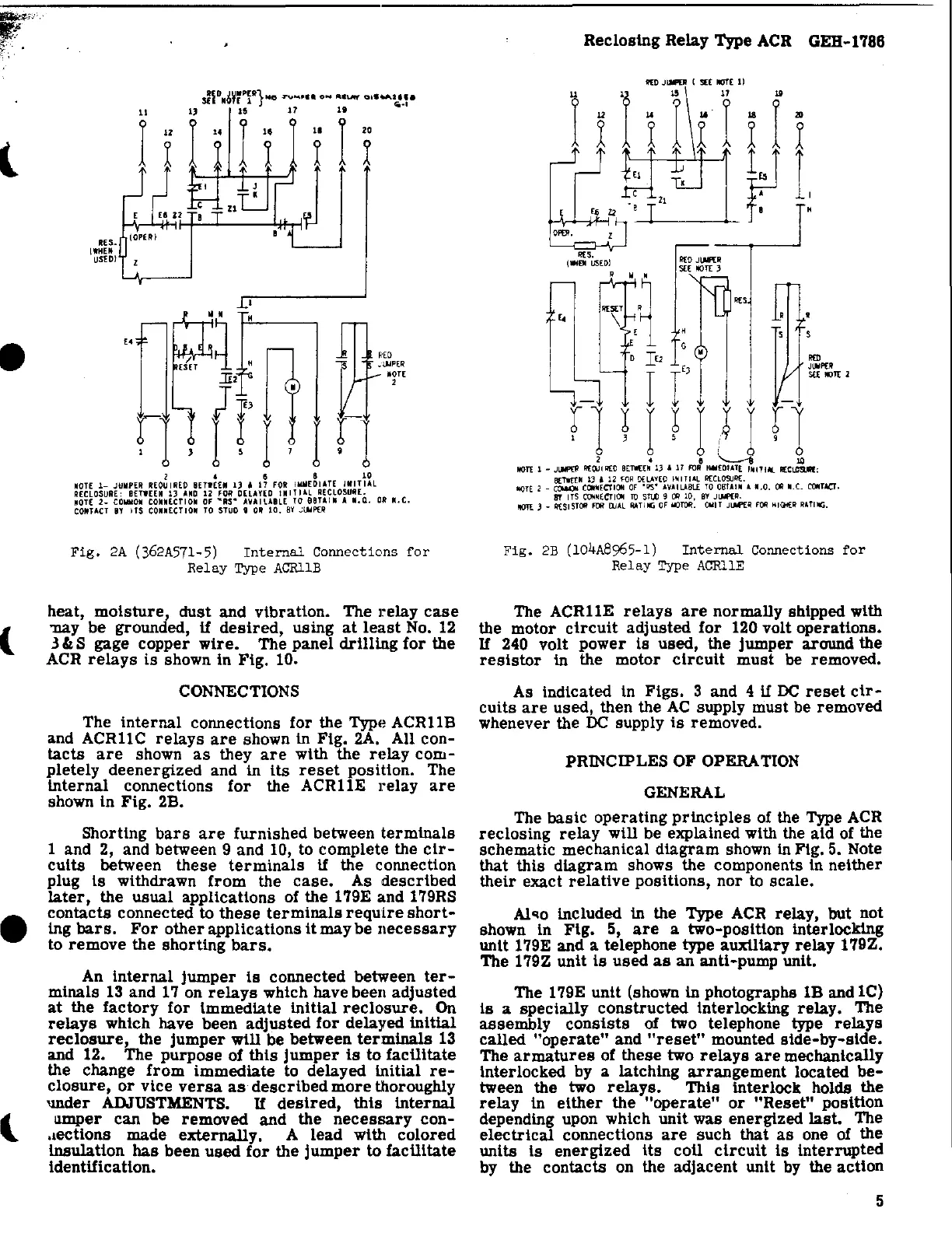
Fig.
2A
(362A57l-5)
Internal
Connections
for
Relay
Type
ACRllB
heat,
moisture,
dust
and
vibration.
The
relay
case
'IllLy
be
grounded, if
desired,
using
at
least
No.
12
3"
S gage
copper
wire.
The
panel
drilling
for
the
ACR
relays
is
shown in Fig. 10.
CONNECTIONS
The
internal
connections for the Type
ACRllB
and
ACRllC
relays
are
shown in Fig. 2A. All
con-
tacts
are
shown
as
they
are
with the
relay
com-
pletely
deenergized
and in Its
reset
position. The
internal
connections
for
the
ACRllE
relay
are
shown In Fig. 2B.
Shorting
bars
are
furnished
between
terminals
1 and 2, and between 9 and 10, to complete the
cir-
cuits
between
these
terminals
if the connection
plug
Is withdrawn
from
the
case.
As
described
later,
the
usual
applications of the 179E and 179RS
contacts
connected to
these
terminals
require
short-
ing
bars.
For
other
applications
It
may
be
necessary
to
remove
the
shorting
bars.
An
Internal
jumper
Is
connected between
ter-
minals
13
and
17
on
relays
which have been
adjusted
at
the
factory
for Immediate
initial
reclosure.
On
relays
which have been
adjusted
for
delayed
initial
reclosure,
the
jumper
will be between
terminals
13
and 12. The
purpose
of
this
jumper
is
to
facilitate
the change
from
immediate
to delayed
initial
re-
closure,
or
vice
versa
as
described
more
thoroughly
'lI1der ADJUSTMENTS.
If
desired,
this
internal
umper
can be
removed
and the
necessary
con-
.1eCtiOnS
made
externally.
A
lead
with
colored
insulation
has
been
used
for
the
jumper
to
facilitate
Identification.
Reclosing
Relay Type ACR GEB-1'186
II({)
JlM'[R
(
S£E
IICJT[
1)
lxl11rlffi
--+---.-21
~
f1
I:
"5.
("Ell
USED)
~o
JI,M'(R
SEE
~IT
,
G
."
o
IE2
RED
I r
_,
~".;"2
rl~I~L*Ir1
2 4 e '----1i
10
~IT
1 -
Jl.M'£1!
f1((lj1
~O
BITIEU
13
"
17
FOR
'IItIEOIA1[
'_IlI/il
Ii(C~:
Bowa-
IJ
"
12
FOR
OEL..t.YEO
INITI
....
L
R(CLOSJI!(.
HOTE
2 -
COtIoOi
C(ItIIEC'I"ON
or
"'IS"
....
V
....
IL..t.BlI
TO
OIfTAIN
A 11.0.
011
_.C.
CONTACT.
Sf
ITS
COfoINECTICtI
TO
STU:l
9
011
10,
BY
Jl.NP(I!.
IIOl£ J -
11(5151011
mI
W
....
L
1lA11J(;
OF
IIOTOR.
OWIT
Jl.Itftl!
FOR
HIGfEI!
RATlIIG.
Fig.
2B
(104A8965-1)
Internal
Connections
for
Relay
Type ACRllE
The
ACRllE
relays
are
normally
shipped with
the motor
circuit
adjusted
for
120 volt operations.
If
240 volt
power
Is used, the
jumper
around the
resistor
in the motor
circuit
must
be removed.
As indicated
In
Figs.
3 and 4 if
DC
reset
cir-
cuits
are
used, then the
AC
supply must be removed
whenever the
DC
supply
is
removed.
PRINCIPLES
OF OPERATION
GENERAL
The basic
operating
principles
of the Type
ACR
reclosing
relay
will be explained with the aid of the
schematic
mechanical
diagram
shown
In
Fig. 5. Note
that
this
diagram
shows the components
In
neither
their
exact
relative
pOSitions,
nor
to
scale.
Al'lo included in the Type ACR relay, but not
shown
In
Fig.
5,
are
a two-position Interlocking
unit 179E and a telephone type
auxiliary
relay
179Z.
The 179Z unit
Is
used
as
an
anti-pump unit.
The 179E
unit
(shown in photographs 1B and
lC)
Is a
specially
constructed
Interlocking
relay.
The
assembly
consists
of
two telephone type
relays
called
"operate"
and
"reset"
mounted
side-by-slde.
The
armatures
of
these
two
relays
are
mechanically
Interlocked by a latching
arrangement
located
be-
tween the two
relays.
This
interlock holds the
relay
in
either
the
"operate"
or
"Reset"
position
depending upon which unit was energized
last.
The
electrical
connections
are
such
that
as
one
of
the
units
Is
energized
Its coll
circuit
Is
Interrupted
by the contacts on the adjacent unit
by
the
action
5


 To Next Page
 Loading...