Installation Instructions
ELECTRICAL REQUIREMENTS
• [)se ONlY the wiring size reconm/ended fin" single
outlet branch circuit.
• Proper current protection is the responsibility
of the owner.
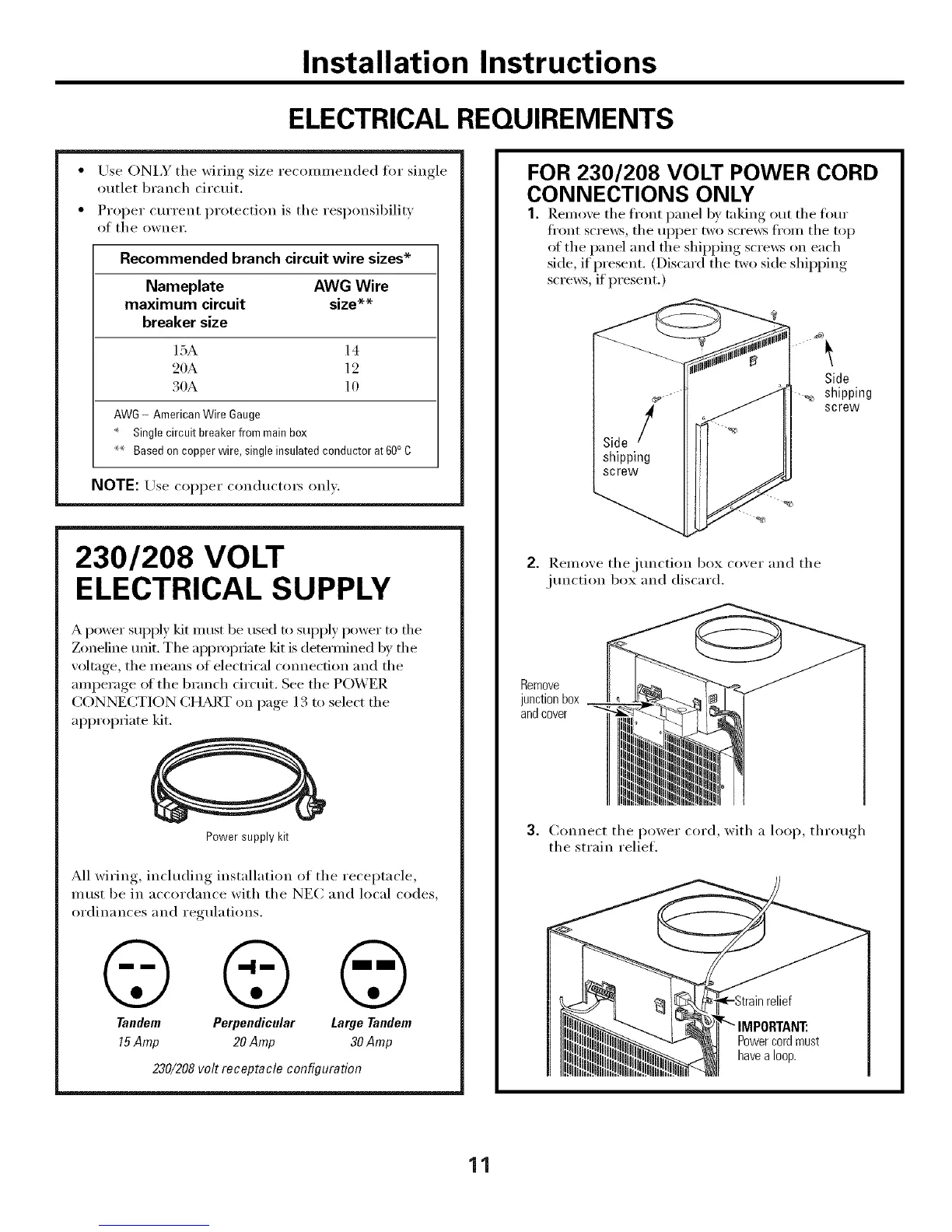
Recommended branch circuit wire sizes*
Nameplate AWG Wire
maximum circuit size**
breaker size
15A 14
20A 12
30A 10
AWG - American Wire Gauge
Singlecircuit breaker from main box
** Based on copper wire, single insulated conductor at 60° C
NOTE: Use COl)per conductm_ only.
230/208 VOLT
ELECTRICAL SUPPLY
A power supi)ly kit must be used to supply power to fl_e
Zoneline trait. The appropfiam kit is detemfined by the
w)ltage, the means of electrical connection and the
amperage of the branch drcuit. See the PO_'ER
CONNECTION CHART on page 13 to select the
ai)i)ropriate kit.
Power supply kit
M1 wirin , including installation of the receptacle,
must be in accordance with the NEC and local codes,
ordinances and regulations.
© © ©
Tandem Perpendicular Large Tandem
15Amp 20 Amp 30 Amp
230/208 volt receptacle configuration
FOR 230/208 VOLT POWER CORD
CONNECTIONS ONLY
1. Remove the tl"ont panel by taking out the tom"
fl'ont scre_vs, the uI)per two scre_v_ fl'om the top
of the panel and the shii)ping scre_vs on each
side, if present. (Discard the two side shii)ping
scrmvs, if present.)
Side
_, shipping
screw
2. ]).emoxe thejtmcti(m box coxer and the
jtmction box and discard.
Remove
junction box
and cover
3. Connect the power cord, with a loop, throm,h
the strain relief.
Powercordmust
havea loop.
11
 Loading...