Installation Instructions
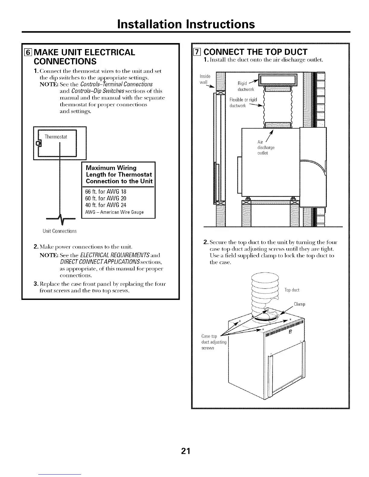
[] MAKE UNIT ELECTRICAL
CONNECTIONS
1.Connect tile themlostat wires to tile unit and set
tile dip switches to tile appropriate settings.
NOTE: See the Controls-TerminalConnections
and Controls-Dip Switches sect.ions of this
mmmal and tile manual with tile separate
thellilOstat ti)i" proper connections
and settings.
Thermostat ]
--r
Unit Connections
Maximum Wiring
Length for Thermostat
Connection to the Unit
66 ft. for AW6 18
60 ft. for AW6 20
40 ft. for AW6 24
AWG AmericanWire Gauge
2. Make power connections to tile trait.
No'rE: See tile ELECTRICALREOUIREMENTS',md
DIRECT CONNECTAPPLICATIONS secdons,
as appropriate, ot this inanual for proper
connections.
3. Replace tile case fl'ont panel b)' replacing tile four
Ji'ont ScI'eWS }lll(l tile two top scre_vs.
[] CONNECT THE TOP DUCT
1. Install tile duct onto tile air discharge outlet.
i!;i!;i!;i!;i!;i!;ii
i
Flexibleorrigid
ducWvork_ '
Airf
discharge
outlet
2. Secm'e tile top duct to tile trait by tm'ning tile fl)m"
case top duct a(!justing scre_vs tmtil they are tight.
Use a field supplied clamp to lock tile top dtlct to
tile case.
Casetop
ductadjusting
screws
Topduct
Clamp
21
 Loading...